Dodge Durango (HB). Manual - part 1380


  Index      Dodge     Dodge Durango (HB) - service repair manual 2005 year


Search            


Content   ..  1378  1379  1380  1381   ..


Dodge Durango (HB). Manual - part 1380


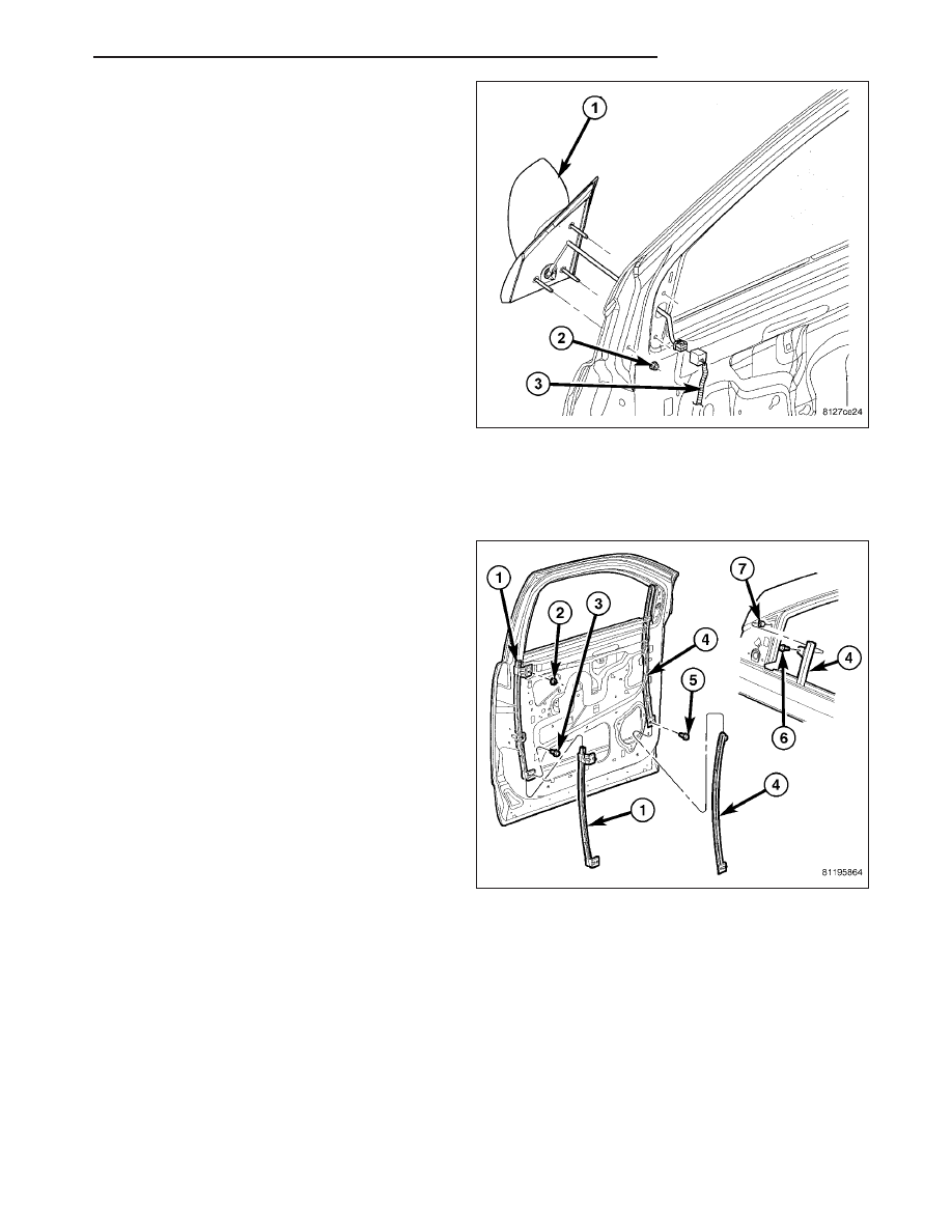
5. Install the side view mirror.

6. Install the nuts and connect the electrical connec-

tor.

7. Install the watershield. (Refer to 23 - BODY/DOOR

- FRONT/WATERSHIELD - INSTALLATION)

LATCH

REMOVAL

1. Remove the watershield. (Refer to 23 - BODY/

DOOR - FRONT/WATERSHIELD - REMOVAL)

2. Remove the bolt (3) and nut (2) and position aside

the rear glass run channel (1).

HB

DOOR - FRONT

23 - 33

3. Remove the latch screws (5).

4. Disconnect the actuator rods (3).

5. Disconnect

the

electrical

connectors

(6)

and

remove the latch.

INSTALLATION

1. Install the latch into the door.

2. Connect the electrical connectors (6).

3. Connect the actuator rods (3).

4. Install the screws and tighten to 10 N·m (85 in.

lbs.).

5. Adjust the latch as needed. (Refer to 23 - BODY/

DOOR - FRONT/LATCH - ADJUSTMENTS)

6. Position the rear glass run channel back and install

the nut and bolt.

7. Tighten the fasteners to 8 N·m (70 in. lbs.).

8. Install the watershield. (Refer to 23 - BODY/DOOR

- FRONT/WATERSHIELD - INSTALLATION) (Refer
to 23 - BODY/DOOR - FRONT/WATERSHIELD -
INSTALLATION)

23 - 34

DOOR - FRONT

HB

ADJUSTMENTS

ADJUSTMENT

1. Locate access hole (3) and remove the trim plug

covering it.

2. Insert a 5/32-inch hex-wrench through hole and

into adjustment screw. Loosen screw.

3. Operate outside handle several times to release

any restriction because of mis-alignment.

4. Tighten adjustment screw to 3 N·m (30 in. lbs.).

5. Test handle for proper operation.

DOOR

REMOVAL

1. Disconnect the door wire harness electrical con-

nector (1) at the a-pillar (2).

2. Using a grease pencil or equivalent, mark the out-

line of the door hinges on the door end to aid
installation.

3. Support the door with a suitable lifting device.

NOTE: The welded washers should not be sepa-
rated from the hinge. If the washers are removed
the door may have to be re-adjusted.

4. Remove the nuts (3) attaching the door hinges (2)

to the door (1).

HB

DOOR - FRONT

23 - 35

INSTALLATION

1. Support the door with a suitable lifting device and

install the door (1) onto the hinges (2).

2. Install the washers, if they were removed previ-

ously, nuts and tighten to 28 N·m (21 ft. lbs.).

3. Connect the electrical connectors (1 & 2).

4. Adjust the door as necessary. (Refer to 23 - BODY/

DOOR - FRONT/DOOR - ADJUSTMENTS)

ADJUSTMENTS

NOTE: For vehicles with four doors, it is recommended that you adjust the rear door before adjusting the
front door. (Refer to 23 - BODY/DOORS - REAR/DOOR - ADJUSTMENTS)

Door adjustment measurements should be taken from stationary or welded body panels like the roof,
rocker or quarter panels.

During adjustment procedures, it is recommended that all the hinge fasteners be loosened except for the
upper most fasteners. Adjustments can be made using the upper bolts to hold the door with final torque
of the fasteners occurring after correct door positioning is achieved.

A suitable body sealant should be used when removing or moving the hinges.

23 - 36

DOOR - FRONT

HB


Content   ..  1378  1379  1380  1381   ..