Dodge Durango (HB). Manual - part 1344


  Index      Dodge     Dodge Durango (HB) - service repair manual 2005 year


Search            


Content   ..  1342  1343  1344  1345   ..


Dodge Durango (HB). Manual - part 1344


C140B- TRANSFER CASE MOTOR CONTROL CIRCUIT LOW (CONTINUED)

3.

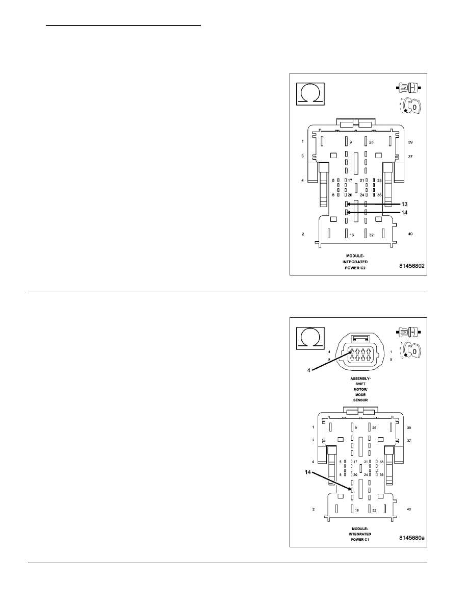
SHIFT MOTOR CIRCUIT RESISTANCE AT PDM CONNECTOR

Disconnect the Power Distribution Module (PDM) C2 connector.

Measure the resistance between the Shift Motor (+) circuit and the
Shift Motor (-) circuit at the PDM C2 connector.

Is the resistance between 40 and 100 ohms?

Yes

>> Replace the Power Distribution Module (PDM).

Perform the TRANSFER CASE VERIFICATION TEST-
VER 1. (Refer to 8 - ELECTRICAL/ELECTRONIC CON-
TROL MODULES/TRANSFER CASE CONTROL MODULE
- DIAGNOSIS AND TESTING)

No

>> Go to 4

4.

(T101) SHIFT MOTOR + (POS) CIRCUIT OPEN

Disconnect the Shift Motor/Mode Sensor Assembly connector.

Measure the resistance of the (T101) Shift Motor + (pos) circuit from
the Shift Motor/Mode Sensor Assembly connector to the Power Distri-
bution Module C2 connector.

Is the resistance above 5.0 ohms?

Yes

>> Repair the (T101) Shift Motor + (pos) circuit for an open.

Perform the TRANSFER CASE VERIFICATION TEST-
VER 1. (Refer to 8 - ELECTRICAL/ELECTRONIC CON-
TROL MODULES/TRANSFER CASE CONTROL MODULE
- DIAGNOSIS AND TESTING)

No

>> Go to 5

HB

TRANSFER CASE - ELECTRICAL DIAGNOSTICS

21 - 781

C140B- TRANSFER CASE MOTOR CONTROL CIRCUIT LOW (CONTINUED)

5.

(T102) SHIFT MOTOR — (NEG) CIRCUIT OPEN

Measure the resistance of the (T102) Shift Motor — (neg) circuit from
the Shift Motor/Mode Sensor Assembly connector to the Power Distri-
bution Module C2 connector.

Is the resistance above 5.0 ohms?

Yes

>> Repair the (T102) Shift Motor — (neg) circuit for an open.

Perform the TRANSFER CASE VERIFICATION TEST-
VER 1. (Refer to 8 - ELECTRICAL/ELECTRONIC CON-
TROL MODULES/TRANSFER CASE CONTROL MODULE
- DIAGNOSIS AND TESTING)

No

>> Go to 6

6.

(T101) SHIFT MOTOR + (POS) CIRCUIT SHORTED TO GROUND

Measure the resistance between ground and the (T101) Shift Motor +
(pos) circuit at the Shift Motor/Mode Sensor Assembly connector.

Is the resistance below 5.0 ohms?

Yes

>> Repair the (T101) Shift Motor + (pos) circuit for a short to

ground.

Perform the TRANSFER CASE VERIFICATION TEST-
VER 1. (Refer to 8 - ELECTRICAL/ELECTRONIC CON-
TROL MODULES/TRANSFER CASE CONTROL MODULE
- DIAGNOSIS AND TESTING)

No

>> Go to 7

21 - 782

TRANSFER CASE - ELECTRICAL DIAGNOSTICS

HB

C140B- TRANSFER CASE MOTOR CONTROL CIRCUIT LOW (CONTINUED)

7.

(T102) SHIFT MOTOR — (NEG) CIRCUIT SHORTED TO GROUND

Measure the resistance between ground and the (T102) Shift Motor —
(neg) circuit at the Shift Motor/Mode Sensor Assembly connector.

Is the resistance below 5.0 ohms?

Yes

>> Repair the (T102) Shift Motor — (neg) circuit for a short to

ground.

Perform the TRANSFER CASE VERIFICATION TEST-
VER 1. (Refer to 8 - ELECTRICAL/ELECTRONIC CON-
TROL MODULES/TRANSFER CASE CONTROL MODULE
- DIAGNOSIS AND TESTING)

No

>> Go to 8

8.

(T101) SHIFT MOTOR + (POS) CIRCUIT SHORTED TO (T102) SHIFT MOTOR — (NEG) CIRCUIT

Measure the resistance between (T101) Shift Motor + (pos) circuit and
the (T102) Shift Motor — (neg) circuit at the Shift Motor/Mode Sensor
Assembly connector.

Is the resistance below 5.0 ohms?

Yes

>> Repair the (T101) Shift Motor + (pos) circuit for a short to

the (T102) Shift Motor — (neg) circuit.

Perform the TRANSFER CASE VERIFICATION TEST-
VER 1. (Refer to 8 - ELECTRICAL/ELECTRONIC CON-
TROL MODULES/TRANSFER CASE CONTROL MODULE
- DIAGNOSIS AND TESTING)

No

>> Replace the Shift Motor/Mode Sensor assembly in accor-

dance with the Service Information.

Perform the TRANSFER CASE VERIFICATION TEST-
VER 1. (Refer to 8 - ELECTRICAL/ELECTRONIC CON-
TROL MODULES/TRANSFER CASE CONTROL MODULE
- DIAGNOSIS AND TESTING)

9.

FRONT CONTROL MODULE

Using the wiring diagram/schematic as a guide, inspect all wiring and connectors that pertain to this circuit.

Were any problems found?

Yes

>> Repair as necessary.

Perform the TRANSFER CASE VERIFICATION TEST-VER 1. (Refer to 8 - ELECTRICAL/ELECTRONIC
CONTROL MODULES/TRANSFER CASE CONTROL MODULE - DIAGNOSIS AND TESTING)

No

>> Replace the Front Control Module in accordance with the Service Information.

Perform the TRANSFER CASE VERIFICATION TEST-VER 1. (Refer to 8 - ELECTRICAL/ELECTRONIC
CONTROL MODULES/TRANSFER CASE CONTROL MODULE - DIAGNOSIS AND TESTING)

HB

TRANSFER CASE - ELECTRICAL DIAGNOSTICS

21 - 783

C140B- TRANSFER CASE MOTOR CONTROL CIRCUIT LOW (CONTINUED)

10.

INTERMITTENT WIRING AND CONNECTORS

The conditions necessary to set this DTC are not present at this time.

Using the wiring diagram/schematic as a guide, inspect the wiring and connectors.

While monitoring the scan tool data relative to this circuit, wiggle test the wiring and connectors.

Look for the data to change or for the DTC to reset during the wiggle test.

Were any problems found?

Yes

>> Repair as necessary.

Perform the TRANSFER CASE VERIFICATION TEST-VER 1. (Refer to 8 - ELECTRICAL/ELECTRONIC
CONTROL MODULES/TRANSFER CASE CONTROL MODULE - DIAGNOSIS AND TESTING)

No

>> Test complete.

21 - 784

TRANSFER CASE - ELECTRICAL DIAGNOSTICS

HB


Content   ..  1342  1343  1344  1345   ..