Dodge Durango (HB). Manual - part 1343


  Index      Dodge     Dodge Durango (HB) - service repair manual 2005 year


Search            


Content   ..  1341  1342  1343  1344   ..


Dodge Durango (HB). Manual - part 1343


C1405- TRANSFER CASE RANGE POSITION SENSOR CIRCUIT HIGH (CONTINUED)

5.

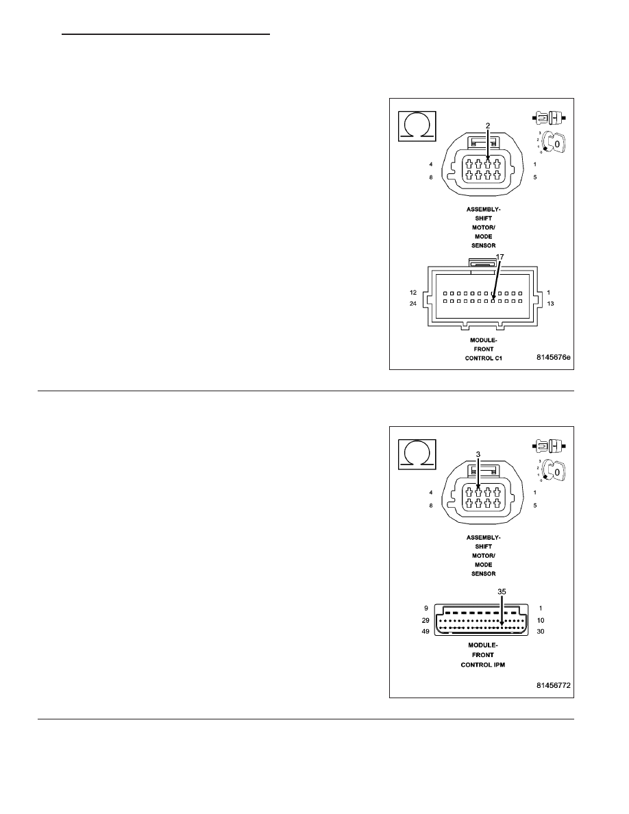
(D201) MODE SENSOR A CIRCUIT OPEN

Turn the ignition off.

Disconnect the Front Control Module C1 connector.

Measure the resistance of the (D201) Mode Sensor A circuit.

Is the resistance above 5.0 ohms?

Yes

>> Repair the (D201) Mode Sensor A circuit for an open.

Perform the TRANSFER CASE VERIFICATION TEST-
VER 1. (Refer to 8 - ELECTRICAL/ELECTRONIC CON-
TROL MODULES/TRANSFER CASE CONTROL MODULE
- DIAGNOSIS AND TESTING)

No

>> Go to 6

6.

(G180) FCM SENSOR RETURN CIRCUIT OPEN

Measure the resistance of the (G180) FCM Sensor Return circuit.

Yes

>> Repair the (G180) FCM Sensor Return circuit for an open.

Perform the TRANSFER CASE VERIFICATION TEST-
VER 1. (Refer to 8 - ELECTRICAL/ELECTRONIC CON-
TROL MODULES/TRANSFER CASE CONTROL MODULE
- DIAGNOSIS AND TESTING)

No

>> Go to 7

HB

TRANSFER CASE - ELECTRICAL DIAGNOSTICS

21 - 777

C1405- TRANSFER CASE RANGE POSITION SENSOR CIRCUIT HIGH (CONTINUED)

7.

FRONT CONTROL MODULE

View repair.

Repair

Replace the Front Control Module in accordance with the Service information.

Perform the TRANSFER CASE VERIFICATION TEST-VER 1. (Refer to 8 - ELECTRICAL/ELECTRONIC
CONTROL MODULES/TRANSFER CASE CONTROL MODULE - DIAGNOSIS AND TESTING)

8.

INTERMITTENT WIRING AND CONNECTORS

The conditions necessary to set this DTC are not present at this time.

Using the wiring diagram/schematic as a guide, inspect the wiring and connectors.

While monitoring the scan tool data relative to this circuit, wiggle test the wiring and connectors.

Look for the data to change or for the DTC to reset during the wiggle test.

Were any problems found?

Yes

>> Repair as necessary.

Perform the TRANSFER CASE VERIFICATION TEST-VER 1. (Refer to 8 - ELECTRICAL/ELECTRONIC
CONTROL MODULES/TRANSFER CASE CONTROL MODULE - DIAGNOSIS AND TESTING)

No

>> Test complete.

21 - 778

TRANSFER CASE - ELECTRICAL DIAGNOSTICS

HB

C140B- TRANSFER CASE MOTOR CONTROL CIRCUIT LOW

HB

TRANSFER CASE - ELECTRICAL DIAGNOSTICS

21 - 779

C140B- TRANSFER CASE MOTOR CONTROL CIRCUIT LOW (CONTINUED)

For a complete wiring diagram Refer to Section 8W

When Monitored:
Ignition on. Battery voltage between 9 and 16 volts.

Set Condition:
FCM detects low voltage on the Transfer Case Motor Control Circuit for 0.5 seconds.

Possible Causes

INTERMITTENT CONDITION

(T101) SHIFT MOTOR + (POS) CIRCUIT OPEN

(T102) SHIFT MOTOR — (NEG) CIRCUIT OPEN

(T101) SHIFT MOTOR + (POS) CIRCUIT SHORTED TO GROUND

(T102) SHIFT MOTOR — (NEG) CIRCUIT SHORTED TO GROUND

(T101) SHIFT MOTOR + (POS) CIRCUIT SHORTED TO (T102) SHIFT MOTOR — (NEG) CIRCUIT

SHIFT MOTOR/MODE SENSOR ASSEMBLY

FRONT CONTROL MODULE

POWER DISTRIBUTION MODULE

Diagnostic Test

1.

SHIFT MOTOR DTC IS ACTIVE

Ignition on, engine not running.

With the scan tool, Clear DTCs.

Move the Shift control to each position, while monitoring the Data Display on the scan tool.

Does the DTC reset?

Yes

>> Go to 2

No

>> Go to 10

2.

SHIFT MOTOR CIRCUIT RESISTANCE AT FCM CONNECTOR

Turn the ignition off.

Remove the Front Control Module (FCM) from the Power Distribution
Module (PDM).

Measure the resistance between the Shift Motor (+) circuit and the
Shift Motor (-) circuit in the FCM connector of the PDM.

Is the resistance between 40 and 100 ohms?

Yes

>> Go to 9

No

>> Go to 3

21 - 780

TRANSFER CASE - ELECTRICAL DIAGNOSTICS

HB


Content   ..  1341  1342  1343  1344   ..