Dodge Durango (HB). Manual - part 1330


  Index      Dodge     Dodge Durango (HB) - service repair manual 2005 year


Search            


Content   ..  1328  1329  1330  1331   ..


Dodge Durango (HB). Manual - part 1330


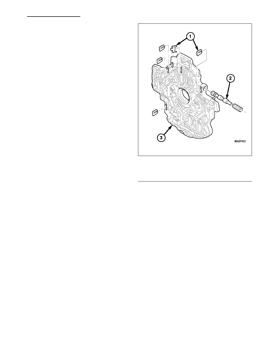
2. Lubricate the oil pump valves with Mopar

T

ATF +4

and install the valve (2), spring, and retainer (1)
into the appropriate oil pump valve body (3) bore.

T/C Switch Valve

1 - RETAINER
2 - T/C SWITCH VALVE
3 - OIL PUMP VALVE BODY

HB

AUTOMATIC TRANSMISSION 545RFE - SERVICE INFORMATION

21 - 725

3. Coat the gears (2, 6) with Mopar

T

ATF +4 and install into their original locations.

4. Place the separator plate (1) onto the oil pump housing (4).

5. Install the screws(7) to hold the separator plate (1) onto the oil pump housing (4). Tighten the screws to 4.5 N·m

(40 in.lbs.).

Oil Pump Housing and Gears

1 - SEPARATOR PLATE

5 - DOWEL (2)

2 - DRIVEN GEAR (2)

6 - DRIVE GEAR

3 - CHECK VALVE

7 - SCREW

4 - PUMP HOUSING

21 - 726

AUTOMATIC TRANSMISSION 545RFE - SERVICE INFORMATION

HB

6. Position the oil pump valve body (6) onto the locating dowels.

7. Seat the two oil pump halves together and install all bolts finger tight.

8. Torque all bolts down slowly starting in the center and working outward. The correct torque is 4.5 N·m (40

in.lbs.).

9. Verify that the oil pump gears rotate freely and smoothly.

10. Position the reaction shaft support (5) onto the oil pump valve body (6).

11. Install and torque the bolts to hold the reaction shaft support (5) to the oil pump valve body (6). The correct

torque is 12 N·m (105 in.lbs.).

SEAL-OIL PUMP FRONT

REMOVAL

1. Remove transmission from the vehicle.

2. Remove the torque converter from the transmission.

3. Using a screw mounted in a slide hammer, remove the oil pump front seal.

Oil Pump Assembly

1 - PUMP HOUSING

4 - SEAL RING (5)

2 - SEAL

5 - REACTION SHAFT SUPPORT

3 - OIL FILTER SEAL

6 - PUMP VALVE BODY

HB

AUTOMATIC TRANSMISSION 545RFE - SERVICE INFORMATION

21 - 727

INSTALLATION

1. Clean seal bore of the oil pump of any residue or

particles from the original seal.

2. Install new oil seal in the oil pump housing using

Seal Installer C-3860-A (1).

SENSOR-OUTPUT SPEED

DESCRIPTION

The Input and Output Speed Sensors are two-wire magnetic pickup devices that generate AC signals as rotation
occurs. They are mounted in the left side of the transmission case and are considered primary inputs to the Trans-
mission Control Module (TCM).

OPERATION

The Input Speed Sensor provides information on how fast the input shaft is rotating. As the teeth of the input clutch
hub pass by the sensor coil, an AC voltage is generated and sent to the TCM. The TCM interprets this information
as input shaft rpm.

The Output Speed Sensor generates an AC signal in a similar fashion, though its coil is excited by rotation of the
rear planetary carrier lugs. The TCM interprets this information as output shaft rpm.

The TCM compares the input and output speed signals to determine the following:

Transmission gear ratio

Speed ratio error detection

CVI calculation

The TCM also compares the input speed signal and the engine speed signal to determine the following:

Torque converter clutch slippage

Torque converter element speed ratio

21 - 728

AUTOMATIC TRANSMISSION 545RFE - SERVICE INFORMATION

HB


Content   ..  1328  1329  1330  1331   ..