Content .. 1326 1327 1328 1329 ..
Dodge Durango (HB). Manual - part 1328
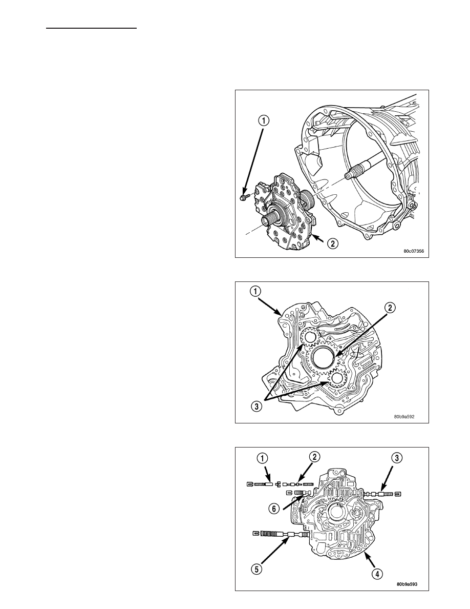
PUMP-OIL
DESCRIPTION
The oil pump (2) is located at the front of the trans-
mission inside the bell housing and behind the trans-
mission front cover.
The oil pump consists of two independent pumps.
The oil pump also contains a number of valves. The
converter clutch switch (3) and control valves (2),
pressure regulator valve (5), and converter pressure
limit valve (6) are all located in the oil pump valve
body.
HB
AUTOMATIC TRANSMISSION 545RFE - SERVICE INFORMATION
21 - 717