Dodge Durango (HB). Manual - part 1326


  Index      Dodge     Dodge Durango (HB) - service repair manual 2005 year


Search            


Content   ..  1324  1325  1326  1327   ..


Dodge Durango (HB). Manual - part 1326


27. Remove the reverse clutch pack (8) from the input clutch retainer.

28. Install the number 2 thrust bearing (18) onto the underdrive hub (17) with outer race against the hub with petro-

leum jelly.

29. Install the underdrive hub (17) into the input clutch retainer.

30. Install the number 3 thrust bearing (1) into the overdrive hub (2) with the outer race against the hub with petro-

leum jelly.

31. Install the overdrive hub (2) into the input clutch retainer.

32. Install the number 4 thrust bearing (5) into the reverse hub with outer race against the hub with petroleum jelly.

33. Install the reverse hub (7) into the input clutch retainer.

34. Install the complete reverse clutch pack (8).

35. Install the reverse reaction plate (9) and snap-ring (10).

36. Push up on reaction plate to allow reverse clutch to move freely.

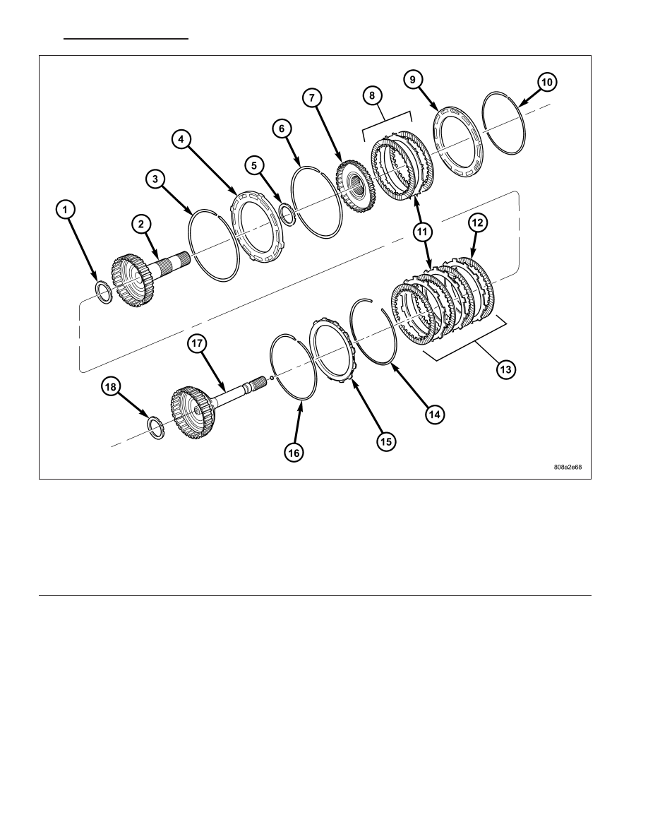
Input Clutch Assembly - Part 2

1 - THRUST BEARING NUMBER 3

10 - SNAP-RING (SELECT)

2 - OD HUB/SHAFT

11 - PLATE

3 - SNAP-RING (WAVE)

12 - DISC

4 - REV/OD REACTION PLATE

13 - OD CLUTCH

5 - THRUST BEARING NUMBER 4

14 - SNAP-RING (TAPERED)

6 - SNAP-RING (FLAT)

15 - UD/OD REACTION PLATE

7 - REVERSE HUB/SHAFT

16 - SNAP-RING (FLAT)

8 - REVERSE CLUTCH

17 - UD HUB/SHAFT

9 - REVERSE REACTION PLATE

18 - THRUST BEARING NUMBER 2

HB

AUTOMATIC TRANSMISSION 545RFE - SERVICE INFORMATION

21 - 709

SENSOR-INPUT SPEED

DESCRIPTION

The Input and Output Speed Sensors are two-wire magnetic pickup devices that generate AC signals as rotation
occurs. They are mounted in the left side of the transmission case and are considered primary inputs to the Trans-
mission Control Module (TCM).

OPERATION

The Input Speed Sensor provides information on how fast the input shaft is rotating. As the teeth of the input clutch
hub pass by the sensor coil, an AC voltage is generated and sent to the TCM. The TCM interprets this information
as input shaft rpm.

The Output Speed Sensor generates an AC signal in a similar fashion, though its coil is excited by rotation of the
rear planetary carrier lugs. The TCM interprets this information as output shaft rpm.

The TCM compares the input and output speed signals to determine the following:

Transmission gear ratio

Speed ratio error detection

CVI calculation

The TCM also compares the input speed signal and the engine speed signal to determine the following:

Torque converter clutch slippage

Torque converter element speed ratio

REMOVAL

1. Raise vehicle.

2. Place a suitable fluid catch pan under the transmis-

sion.

3. Remove the wiring connector from the input speed

sensor (3).

4. Remove the bolt holding the input speed sensor to

the transmission case.

5. Remove the input speed sensor (3) from the trans-

mission case.

21 - 710

AUTOMATIC TRANSMISSION 545RFE - SERVICE INFORMATION

HB

INSTALLATION

1. Install the input speed sensor (3) into the transmis-

sion case.

2. Install the bolt to hold the input speed sensor (3)

into the transmission case. Tighten the bolt to 11.9
N·m (105 in.lbs.).

3. Install the wiring connector onto the input speed

sensor.

4. Verify the transmission fluid level. Add fluid as nec-

essary.

5. Lower vehicle.

SENSOR-LINE PRESSURE

DESCRIPTION

The TCM utilizes a closed-loop system to control transmission line pressure. The system contains a variable force
style solenoid, the Pressure Control Solenoid, mounted on the side of the solenoid and pressure switch assembly.
The solenoid is duty cycle controlled by the TCM to vent the unnecessary line pressure supplied by the oil pump
back to the sump. The system also contains a variable pressure style sensor, the Line Pressure Sensor, which is a
direct input to the TCM. The line pressure solenoid monitors the transmission line pressure and completes the feed-
back loop to the TCM. The TCM uses this information to adjust its control of the pressure control solenoid to
achieve the desired line pressure.

OPERATION

The TCM calculates the desired line pressure based upon inputs from the transmission and engine. The TCM cal-
culates the torque input to the transmission and uses that information as the primary input to the calculation. The
line pressure is set to a predetermined value during shifts and when the transmission is in the PARK and NEUTRAL
positions. This is done to ensure consistent shift quality. During all other operation, the actual line pressure is com-
pared to the desired line pressure and adjustments are made to the pressure control solenoid duty cycle.

HB

AUTOMATIC TRANSMISSION 545RFE - SERVICE INFORMATION

21 - 711

REMOVAL

1. Raise vehicle.

2. Place a suitable fluid catch pan under the transmis-

sion.

3. Remove the wiring connector from the line pres-

sure sensor (2).

4. Remove the bolt holding the line pressure sensor

(2) to the transmission case.

5. Remove the line pressure sensor (2) from the

transmission case.

INSTALLATION

1. Install the line pressure sensor (2) into the trans-

mission case.

2. Install the bolt to hold the line pressure sensor (2)

into the transmission case. Tighten the bolt to 11.9
N·m (105 in.lbs.).

3. Install the wiring connector onto the line pressure

sensor (2).

4. Verify the transmission fluid level. Add fluid as nec-

essary.

5. Lower vehicle.

21 - 712

AUTOMATIC TRANSMISSION 545RFE - SERVICE INFORMATION

HB


Content   ..  1324  1325  1326  1327   ..