Content .. 1322 1323 1324 1325 ..
Dodge Durango (HB). Manual - part 1324
16. Remove the UD/OD balance piston (6) and piston return spring (9) from the input clutch retainer (13).
17. Remove the underdrive piston (8) from the input clutch retainer (13).
NOTE: Both the UD/OD balance piston and the underdrive piston have seals molded onto them. If the seal
is damaged, do not attempt to install a new seal onto the piston. The piston/seal must be replaced as an
assembly.
18. Remove the input clutch retainer tapered snap-ring (5).
19. Separate input clutch retainer (13) from input clutch hub (1).
20. Separate OD/reverse piston (15) from input clutch hub retainer (13).
21. Remove all seals and o-rings from the input shaft and input hub. The o-rings on the input hub are color coded.
Be sure to make note of which o-ring belongs in which location.
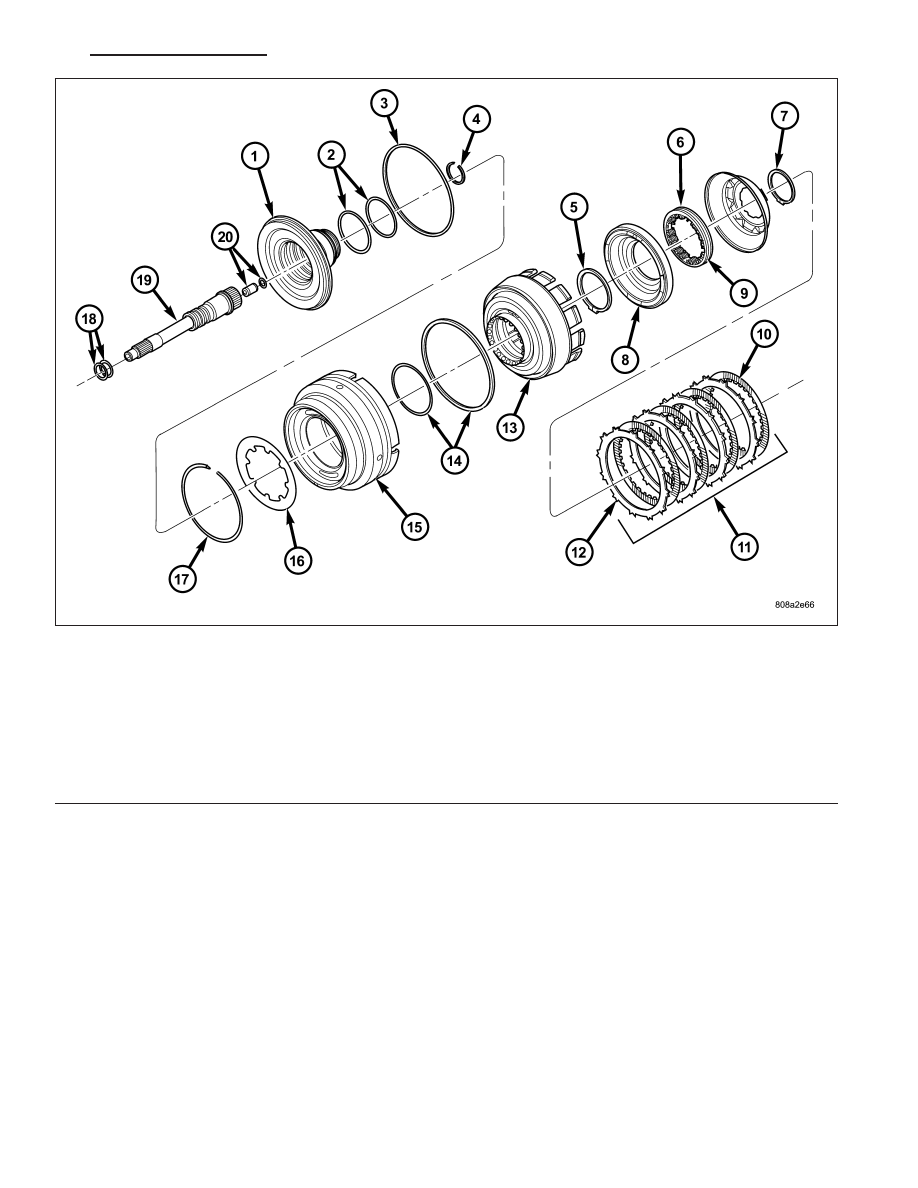
Input Clutch Assembly - Part 1
1 - INPUT CLUTCH HUB
11 - UD CLUTCH
2 - O-RING SEALS
12 - PLATE
3 - SEAL
13 - CLUTCH RETAINER
4 - SNAP-RING
14 - SEAL
5 - SNAP-RING
15 - OD/REV PISTON
6 - UD BALANCE PISTON
16 - BELLEVILLE SPRING
7 - SNAP-RING
17 - SNAP-RING
8 - UD PISTON
18 - SEAL RINGS
9 - SPRING
19 - INPUT SHAFT
10 - DISC
20 - LUBRICATION CHECK VALVE AND SNAP-RING
HB
AUTOMATIC TRANSMISSION 545RFE - SERVICE INFORMATION
21 - 701