Dodge Durango (HB). Manual - part 1329


  Index      Dodge     Dodge Durango (HB) - service repair manual 2005 year


Search            


Content   ..  1327  1328  1329  1330   ..


Dodge Durango (HB). Manual - part 1329


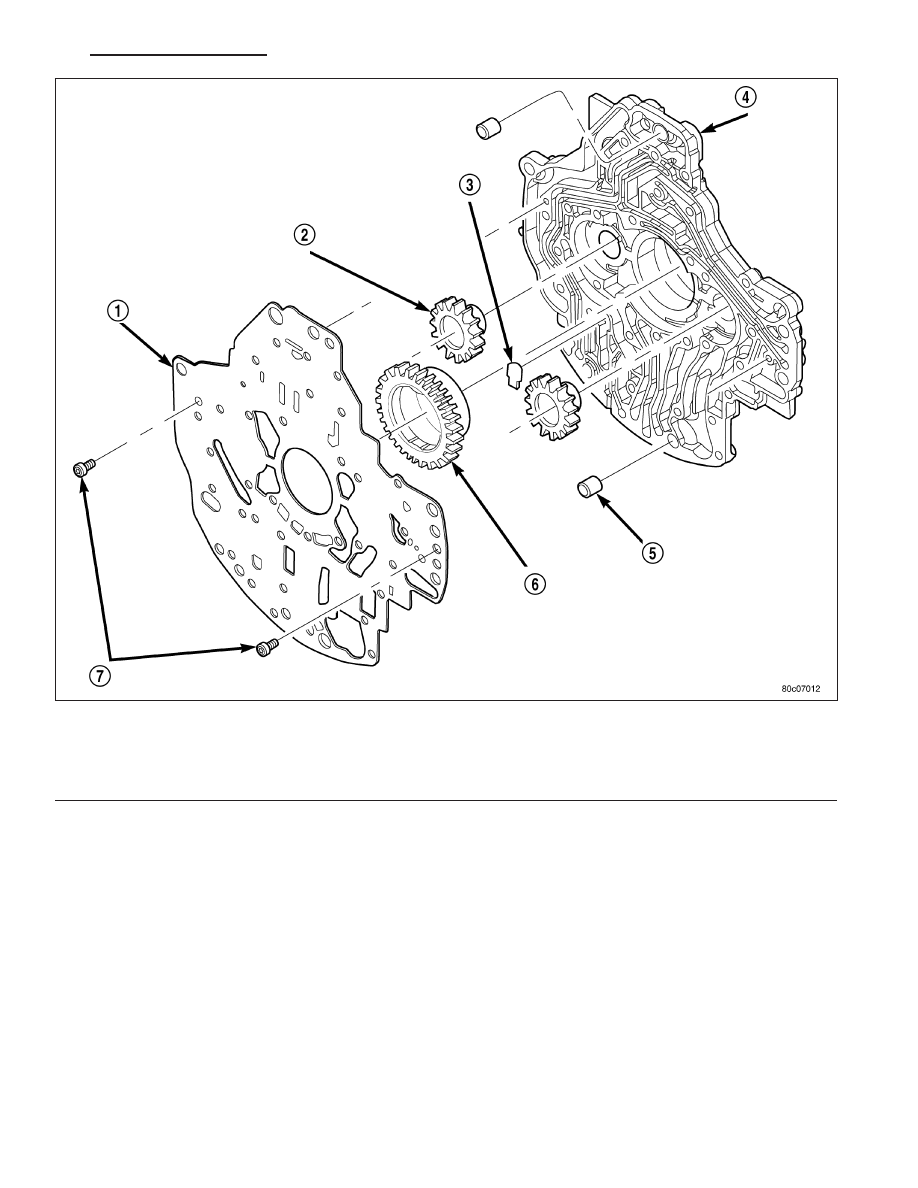
5. Remove the screws (7) holding the separator plate (1) onto the oil pump housing (4).

6. Remove the separator plate (1) from the oil pump housing (4).

7. Mark all gears for location. The gears are select fit and if the oil pump is to be reused, the gears must be

returned to their original locations.

8. Remove the oil pump gears (2, 6) from the oil pump housing (4).

Oil Pump Housing and Gears

1 - SEPARATOR PLATE

5 - DOWEL (2)

2 - DRIVEN GEAR (2)

6 - DRIVE GEAR

3 - CHECK VALVE

7 - SCREW

4 - PUMP HOUSING

HB

AUTOMATIC TRANSMISSION 545RFE - SERVICE INFORMATION

21 - 721

9. Remove the oil pump valve retainers (1) and asso-

ciated valve (2) and spring one at a time. Mark the
combination of components as a group and tag
them as to the location from which they were
removed.

T/C Switch Valve

1 - RETAINER
2 - T/C SWITCH VALVE
3 - OIL PUMP VALVE BODY

21 - 722

AUTOMATIC TRANSMISSION 545RFE - SERVICE INFORMATION

HB

10. Remove the T/C regulator valve (1), T/C limit

valve (2), and regulator valve (3).

CLEANING

Clean pump and support components with solvent and dry them with compressed air.

INSPECTION

Check condition of the seal rings and thrust washer on the reaction shaft support. The seal rings do not need to be
replaced unless cracked, broken, or severely worn.

Inspect the pump and support components. Replace the pump or support if the seal ring grooves or machined sur-
faces are worn, scored, pitted, or damaged. Replace the pump gears if pitted, worn chipped, or damaged.

Inspect the pump reaction shaft support bushings. Replace either bushing only if heavily worn, scored or damaged.
It is not necessary to replace the bushings unless they are actually damaged.

Inspect the valves and plugs for scratches, burrs, nicks, or scores. Minor surface scratches on steel valves and
plugs can be removed with crocus cloth but do not round off the edges of the valve or plug lands. Maintaining
sharpness of these edges is vitally important. The edges prevent foreign matter from lodging between the valves
and plugs and the bore.

Inspect all the valve and plug bores in the oil pump cover. Use a penlight to view the bore interiors. Replace the oil
pump if any bores are distorted or scored. Inspect all of the valve springs. The springs must be free of distortion,
warpage or broken coils.

Trial fit each valve and plug in its bore to check freedom of operation. When clean and dry, the valves and plugs
should drop freely into the bores.

Oil Pump Valve Body

1 - T/C REGULATOR VALVE
2 - T/C LIMIT VALVE
3 - REGULATOR VALVE
4 - OIL PUMP VALVE BODY

HB

AUTOMATIC TRANSMISSION 545RFE - SERVICE INFORMATION

21 - 723

ASSEMBLY

NOTE: Clean and inspect all components. Make sure that all passages are thoroughly cleaned and are free
from dirt or debris. Make sure that all valves move freely in their proper bore. Make sure that all gear pock-
ets and bushings are free from excessive wear and scoring. Replace the oil pump if any excessive wear or
scoring is found.

1. Install the T/C regulator valve (1), T/C limit valve

(2), and regulator valve (3).

Oil Pump Valve Body

1 - T/C REGULATOR VALVE
2 - T/C LIMIT VALVE
3 - REGULATOR VALVE
4 - OIL PUMP VALVE BODY

21 - 724

AUTOMATIC TRANSMISSION 545RFE - SERVICE INFORMATION

HB


Content   ..  1327  1328  1329  1330   ..