Dodge Durango (HB). Manual - part 1285


  Index      Dodge     Dodge Durango (HB) - service repair manual 2005 year


Search            


Content   ..  1283  1284  1285  1286   ..


Dodge Durango (HB). Manual - part 1285


P0935-LINE PRESSURE SENSOR CIRCUIT HIGH (CONTINUED)

2.

PCM AND WIRING

Turn the ignition off to the lock position.

Remove the Starter Relay.

NOTE: Removal of the Starter Relay is to prevent a Transmission, NO RESPONSE, condition and disable the
starter.
Install the Transmission Simulator, Miller tool #8333.

NOTE: Check connectors - Clean/repair as necessary.
Ignition on, engine not running.

With the scan tool, monitor the Line Pressure.

Using the Transmission Simulator, set the rotary switch to each of the 3 line pressure positions.

NOTE: The readings should be within ±14 kPa or 2.0 PSI on the scan tool of the pressure reading specified
on Transmission Simulator.

Does the 3 line pressures on the scan tool match the Line pressure readings on the Transmission Sim-
ulator?

Yes

>> Replace the Line Pressure Sensor per the Service Information.

Perform 45RFE/545RFE TRANSMISSION VERIFICATION TEST - VER 1.

No

>> Go To 3

3.

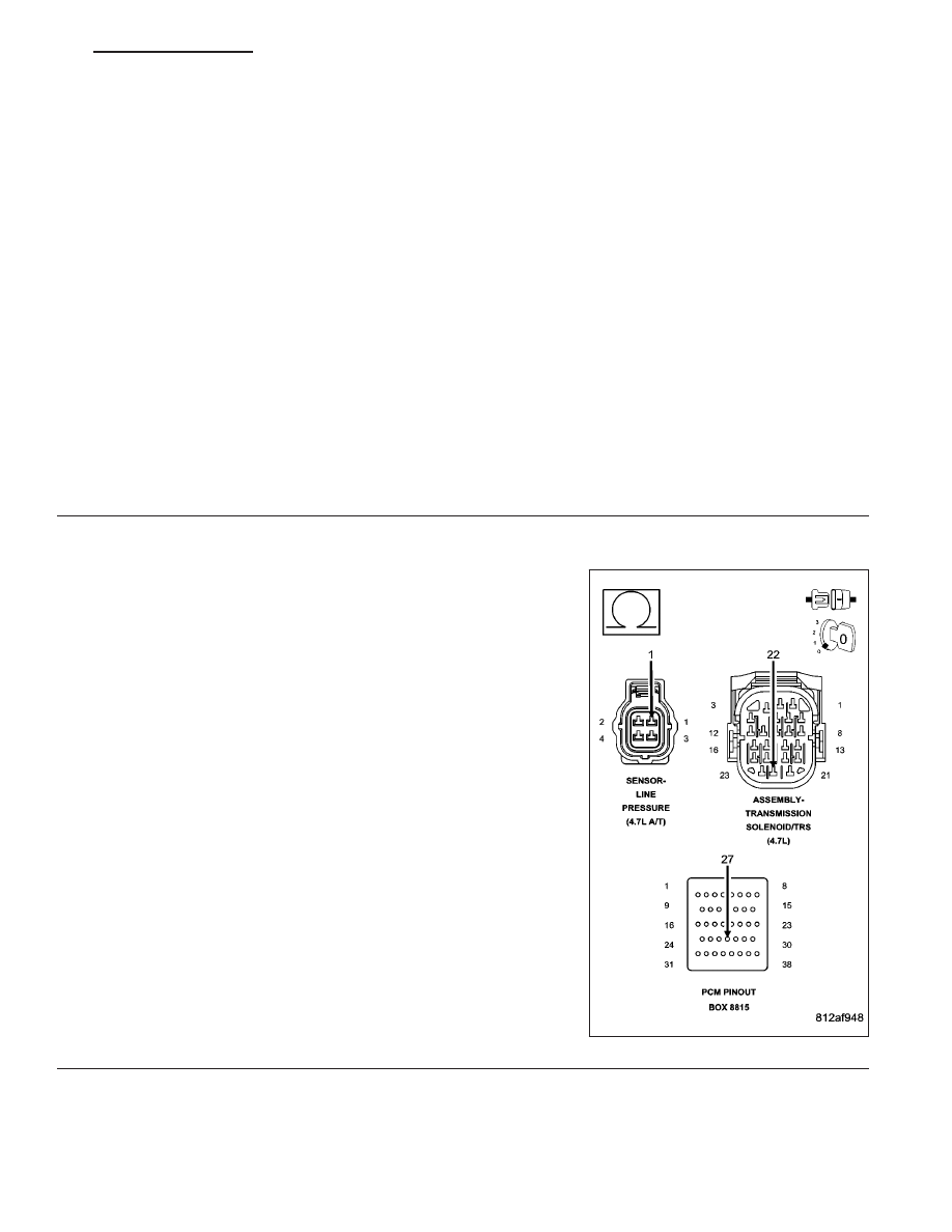
(K900) SENSOR GROUND CIRCUIT OPEN

Turn the ignition off to the lock position.

Disconnect the Transmission Simulator, Miller tool #8333.

Disconnect the PCM C2 harness connector and connect Miller tool
#8815.

CAUTION: Do not probe the PCM harness connectors. Probing
the PCM harness connectors will damage the PCM terminals
resulting in poor terminal to pin connection. Install Miller tool
#8815 to perform diagnosis.
Measure the resistance of the (K900) Sensor Ground circuit from the
Line Pressure Sensor harness connector to the appropriate terminal of
Miller tool #8815.

Is the resistance above 5.0 ohms?

Yes

>> Repair the (K900) Sensor Ground circuit for an open.

Perform 45RFE/545RFE TRANSMISSION VERIFICATION
TEST - VER 1.

No

>> Go To 4

HB

AUTOMATIC TRANSMISSION 545RFE - ELECTRICAL DIAGNOSTICS

21 - 545

P0935-LINE PRESSURE SENSOR CIRCUIT HIGH (CONTINUED)

4.

(T38) LINE PRESSURE SENSOR SIGNAL CIRCUIT OPEN

Disconnect the PCM C4 harness connector and connect Miller tool
#8815.

Measure the resistance of the (T38) Line Pressure Sensor Signal cir-
cuit from the Line Pressure Sensor harness connector to the appropri-
ate terminal of Miller tool #8815.

Is the resistance above 5.0 ohms?

Yes

>> Repair the (T38) Line Pressure Sensor Signal circuit for an

open.

Perform 45RFE/545RFE TRANSMISSION VERIFICATION
TEST - VER 1.

No

>> Go To 5

5.

(T38) LINE PRESSURE SENSOR SIGNAL CIRCUIT SHORT TO VOLTAGE

Remove the Transmission Control Relay.

Connect a jumper wire between the (A104) Fused B+ circuit and the
(T16) Transmission Control Relay Output circuit in the Transmission
Control Relay connector.

Ignition on, engine not running.

Measure the voltage of the (T38) Line Pressure Sensor Signal circuit.

Is the voltage above 5.5 volts?

Yes

>> Repair the (T38) Line Pressure Sensor Signal circuit for a

short to voltage.

Perform 45RFE/545RFE TRANSMISSION VERIFICATION
TEST - VER 1.

No

>> Using the schematics as a guide, check the Powertrain

Control Module (PCM) terminals for corrosion, damage, or
terminal push out. Pay particular attention to all power and
ground circuits. If no problems are found, replace the PCM
per the Service Information. With the scan tool, perform
QUICK LEARN.

Perform 45RFE/545RFE TRANSMISSION VERIFICATION
TEST - VER 1.

21 - 546

AUTOMATIC TRANSMISSION 545RFE - ELECTRICAL DIAGNOSTICS

HB

P0935-LINE PRESSURE SENSOR CIRCUIT HIGH (CONTINUED)

6.

INTERMITTENT WIRING AND CONNECTORS

The conditions necessary to set this DTC are not present at this time.

Using the schematics as a guide, inspect the wiring and connectors specific to this circuit.

Wiggle the wires while checking for shorted and open circuits.

With the scan tool, check the EATX DTC EVENT DATA to help identify the conditions in which the DTC was set.

Where there any problems found?

Yes

>> Repair as necessary.

Perform 45RFE/545RFE TRANSMISSION VERIFICATION TEST - VER 1.

No

>> Test Complete.

HB

AUTOMATIC TRANSMISSION 545RFE - ELECTRICAL DIAGNOSTICS

21 - 547

P0944-LOSS OF HYDRAULIC PUMP PRIME

For the Transmission circuit diagram (Refer to 21 - TRANSMISSION/TRANSAXLE/AUTOMATIC - 45RFE/545RFE -
SCHEMATICS AND DIAGRAMS)

For a complete wiring diagram Refer to Section 8W

When Monitored:
If the transmission is slipping in any forward gear and all the pressure switches are not indicating pressure, a
loss of prime test is run.

Set Condition:
If the transmission begins to slip in a forward gear and all the pressure switch(s) that should be closed are
open a loss of prime test begins. Available elements are turned on by the PCM to see if pump prime exists.
The DTC sets if no pressure switch(s) respond.

Possible Causes

SHIFT LEVER OUT OF ADJUSTMENT

INPROPER FLUID LEVEL

CRACKED OR IMPROPERLY INSTALLED PRIMARY OIL FILTER OR SEAL

LOOSE COOLER RETURN FILTER

STUCK OR STICKING MAIN REGULATOR VALVE

TRANSMISSION OIL PUMP

Always perform the Pre-Diagnostic Troubleshooting procedure before proceeding. (Refer to 21 - TRANSMIS-
SION/TRANSAXLE/AUTOMATIC - 45RFE/545RFE - DIAGNOSIS AND TESTING).

Theory of Operation

The Loss of prime test is used to prevent transmission defaults and erroneous fault codes during temporary loss of
pump prime that may occur with low transmission fluid under severe braking conditions, start-up, etc. and to point
towards more subtle problems such as a plugged or cracked oil filter.

The Loss of Prime DTC is set by a loss of hydraulic pressure in the transmission system. This condition, if sus-
tained, will result in the vehicle being unable to move.

Diagnostic Test

1.

SHIFT LEVER POSITION TEST

Using the scan tool, perform a Shift Lever Position test. Follow the instructions on the scan tool.

Did the Shift Lever Position Test pass?

Yes

>> Go To 2

No

>> Refer to the Transmission category and perform the appropriate symptom.

Perform 45RFE/545RFE TRANSMISSION VERIFICATION TEST - VER 1.

21 - 548

AUTOMATIC TRANSMISSION 545RFE - ELECTRICAL DIAGNOSTICS

HB


Content   ..  1283  1284  1285  1286   ..