Dodge Durango (HB). Manual - part 1228


  Index      Dodge     Dodge Durango (HB) - service repair manual 2005 year


Search            


Content   ..  1226  1227  1228  1229   ..


Dodge Durango (HB). Manual - part 1228


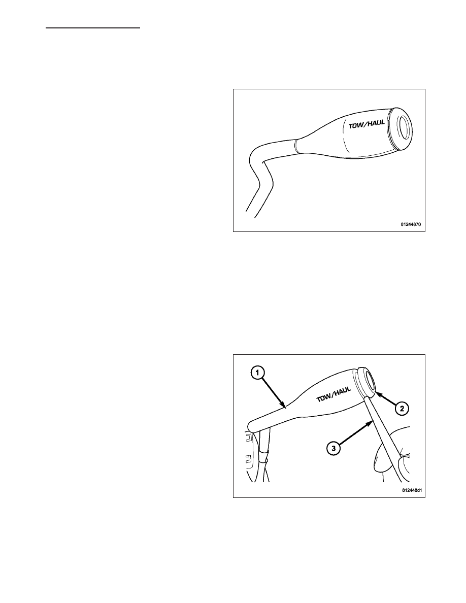
SWITCH-TOW/HAUL OVERDRIVE

DESCRIPTION

The tow/haul overdrive OFF (control) switch is located
in the shift lever arm. The switch is a momentary con-
tact device that signals the PCM to toggle current sta-
tus of the overdrive function.

OPERATION

At key-on, overdrive operation is allowed. Pressing the switch once causes the tow/haul overdrive OFF mode to be
entered and the Tow/Haul lamp to be illuminated. Pressing the switch a second time causes normal overdrive oper-
ation to be restored and the tow/haul lamp to be turned off. The tow/haul overdrive OFF mode defaults to ON after
the ignition switch is cycled OFF and ON. The normal position for the control switch is the ON position. The switch
must be in this position to energize the solenoid and allow a 3-4 upshift. The control switch indicator light illuminates
only when the tow/haul overdrive switch is turned to the OFF position, or when illuminated by the transmission
control module.

REMOVAL

1. Using a plastic trim tool, remove the tow/haul over-

drive off switch retainer (2) from the shift lever (1).

HB

AUTOMATIC TRANSMISSION 42RLE - SERVICE INFORMATION

21 - 317

2. Pull the switch (2) outwards to release it from the

connector in the lever (1)

INSTALLATION

NOTE: There is enough slack in the wire to pull out the connector from the lever.

1. Pull the connector (2) out of the lever (1) just

enough to grasp it.

CAUTION: Be careful not to bend the pins on the
tow/haul overdrive off switch. Use care when
installing the switch, as it is not indexed, and can
be accidentally installed incorrectly.

2. Install the tow/haul overdrive off switch (3) into the

connector (2)

3. Push the tow/haul overdrive off switch (3) and wir-

ing into the shift lever (1).

4. Install the tow/haul overdrive off switch retainer

onto the shift lever.

RELAY-TRANSMISSION CONTROL

DESCRIPTION

The relay is supplied fused B+ voltage, energized by the TCM, and is used to supply power to the solenoid pack
when the transmission is in normal operating mode.

OPERATION

When the relay is “off”, no power is supplied to the solenoid pack and the transmission is in “limp-in” mode. After a
controller reset, the TCM energizes the relay. Prior to this, the TCM verifies that the contacts are open by checking
for no voltage at the switched battery terminals. After this is verified, the voltage at the solenoid pack pressure
switches is checked. After the relay is energized, the TCM monitors the terminals to verify that the voltage is greater
than 3 volts.

21 - 318

AUTOMATIC TRANSMISSION 42RLE - SERVICE INFORMATION

HB

SENSOR-TRANSMISSION RANGE

DESCRIPTION

The Transmission Range Sensor (TRS) (2) is mounted
to the top of the valve body inside the transmission
and can only be serviced by removing the valve body
assembly. The electrical connector extends through
the transmission case.

The Transmission Range Sensor (TRS) has four
switch contacts that monitor shift lever position and
send the information to the PCM.

OPERATION

The Transmission Range Sensor (TRS) communicates shift lever position (SLP) to the TCM as a combination of
open and closed switches. Each shift lever position has an assigned combination of switch states (open/closed) that
the TCM receives from four sense circuits. The TCM interprets this information and determines the appropriate
transmission gear position and shift schedule.

Since there are four switches, there are 16 possible combinations of open and closed switches (codes). Seven of
these codes are related to gear position and three are recognized as “between gear” codes. This results in six
codes which should never occur. These are called “invalid” codes. An invalid code will result in a DTC, and the TCM
will then determine the shift lever position based on pressure switch data. This allows reasonably normal transmis-
sion operation with a TRS failure.

TRS SWITCH STATES

SLP

T42

T41

T3

T1

P

CL

CL

CL

OP

R

CL

OP

OP

OP

N

CL

CL

OP

CL

D

OP

OP

OP

CL

2

OP

OP

CL

OP

1

CL

OP

CL

CL

HB

AUTOMATIC TRANSMISSION 42RLE - SERVICE INFORMATION

21 - 319

REMOVAL

1. Remove valve body assembly from vehicle. (Refer

to 21 - TRANSMISSION/AUTOMATIC - 42RLE/
VALVE BODY - REMOVAL)

2. Remove the manual shaft seal (1).

3. Remove manual shaft/TRS retaining screw (1).

4. Slide TRS off of manual valve shaft.

21 - 320

AUTOMATIC TRANSMISSION 42RLE - SERVICE INFORMATION

HB


Content   ..  1226  1227  1228  1229   ..