Dodge Durango (HB). Manual - part 1195


  Index      Dodge     Dodge Durango (HB) - service repair manual 2005 year


Search            


Content   ..  1193  1194  1195  1196   ..


Dodge Durango (HB). Manual - part 1195


3. Clutch circuit leaks are indicated if pressures do not fall within the specified pressure range.

4. If the overdrive clutch pressure is greater than 5 psi in Step 6 of Test Three, a worn reaction shaft seal ring or

a defective solenoid assembly is indicated.

5. If the underdrive clutch pressure is greater than 5 psi in Step 4 of Test Two-A, a defective solenoid/pressure

switch assembly or controller is the cause.

ALL PRESSURE SPECIFICATIONS ARE PSI (on hoist, with wheels free to turn)

Gear Selector

Position

Actual Gear

PRESSURE TAPS

Under-

drive

Clutch

Over-

drive

Clutch

Reverse

Clutch

Torque

Converter

Clutch

Off

Torque

Converter

Clutch

On

2/4

Clutch

Low/

Reverse

Clutch

PARK - 0 mph *

PARK

0-2

0-5

0-2

60-110

45-100

0-2

115-145

REVERSE - 0
mph *

REVERSE

0-2

0-7

165-235

50-100

35-85

0-2

165-235

NEUTRAL - 0
mph *

NEUTRAL

0-2

0-5

0-2

60-110

45-100

0-2

115-145

Low - 20 mph #

FIRST

110-145

0-5

0-2

60-110

45-100

0-2

115-145

Third - 30 mph #

SECOND

110-145

0-5

0-2

60-110

45-100

115-145

0-2

Third - 45 mph #

DIRECT

75-95

75-95

0-2

60-90

45-80

0-2

0-2

OD - 30 mph #

OVERDRIVE

0-2

75-95

0-2

60-90

45-80

75-95

0-2

OD - 50 mph #

OVERDRIVE
WITH TCC

0-2

75-95

0-2

0-5

60-95

75-95

0-2

* Engine Speed at 1500 rpm

# CAUTION: Both wheels must be turning at same speed.

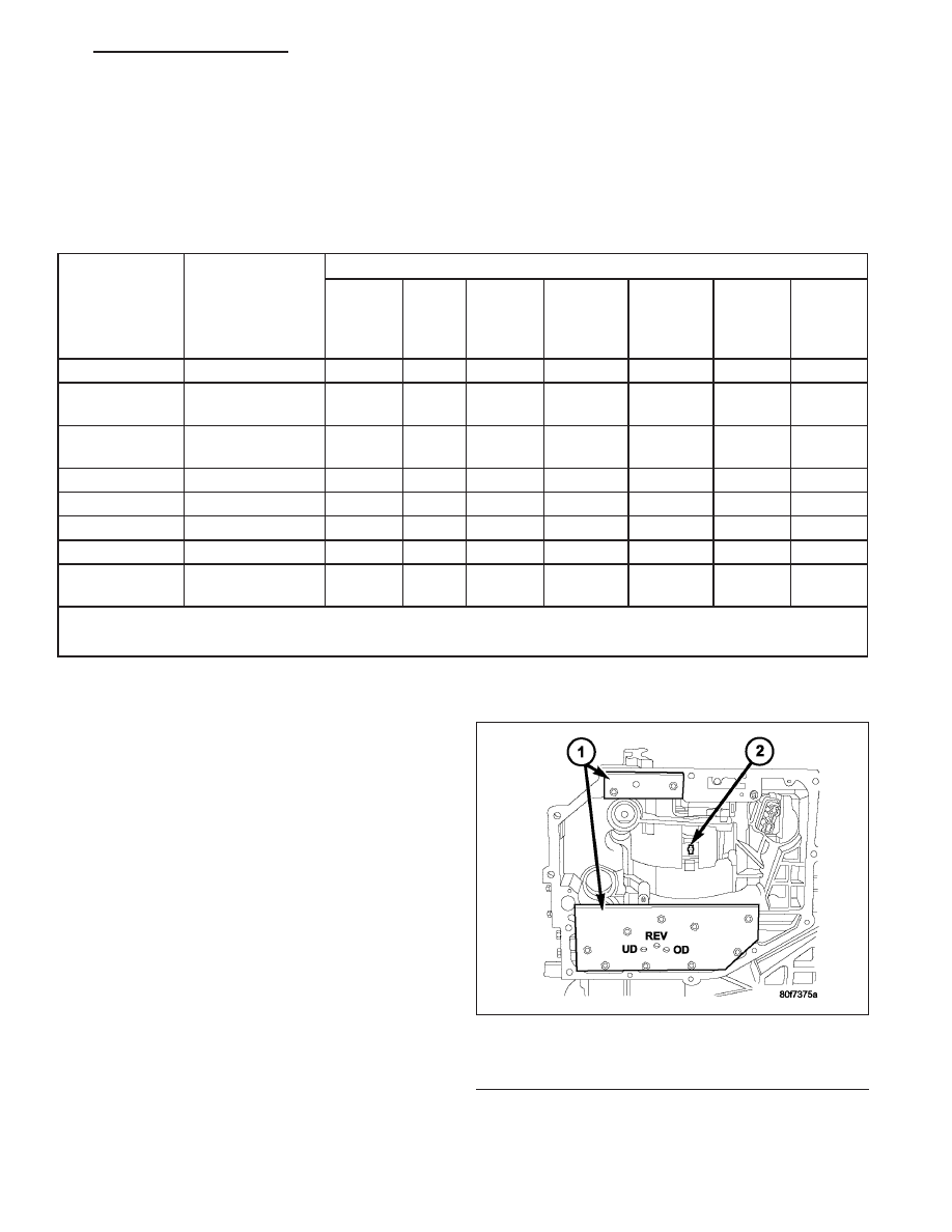
CLUTCH AIR PRESSURE TESTS

Inoperative clutches can be located by substituting air
pressure for fluid pressure. The clutches may be
tested by applying air pressure to their respective pas-
sages after the valve body has been removed. Use
Special Tool 6599-1 (1) and 6599-2 (1) to perform test.

To make air pressure tests, proceed as follows:

NOTE: The compressed air supply must be free of
all dirt and moisture. Use a pressure of 30 psi.

1. Remove oil pan and valve body. (Refer to 21 -

TRANSMISSION/AUTOMATIC

-

42RLE/VALVE

BODY - REMOVAL)

2. Apply air pressure to the holes in the special tool

(1), one at a time.

3. Listen for the clutch to apply. It will give a slight

thud sound. If a large amount of air is heard escap-
ing, the transmission must be removed from vehi-
cle, disassembled and all seals inspected.

Air Pressure Test Plate

1 - AIR PRESSURE TEST PLATES
2 - 2/4 CLUTCH RETAINER HOLE

HB

AUTOMATIC TRANSMISSION 42RLE - SERVICE INFORMATION

21 - 185

2/4 CLUTCH

Apply air pressure to the feed hole located on the 2/4 clutch retainer (2). Look in the area where the 2/4 piston
contacts the first separator plate and watch carefully for the 2/4 piston to move rearward. The piston should return
to its original position after the air pressure is removed.

OVERDRIVE CLUTCH

Apply air pressure to the overdrive clutch apply passage and watch for the push/pull piston to move forward. The
piston should return to its starting position when the air pressure is removed.

REVERSE CLUTCH

Apply air pressure to the reverse clutch apply passage and watch for the push/pull piston to move rearward. The
piston should return to its starting position when the air pressure is removed.

LOW/REVERSE CLUTCH

Apply air pressure to the low/reverse clutch feed hole passage. Look in the area where the low/reverse piston con-
tacts the first separator plate. Watch carefully for the piston to move forward. The piston should return to its original
position after the air pressure is removed.

UNDERDRIVE CLUTCH

Because this clutch piston cannot be seen, its opera-
tion is checked by function. Use an air nozzle (2) to
apply air pressure is to the low/reverse or the 2/4
clutch opening in Test Plate 6599-1 (2). This locks the
output shaft. Use a piece of rubber hose wrapped
around the input shaft and a pair of clamp-on pliers to
turn the input shaft. Next apply air pressure to the
underdrive clutch. The input shaft should not rotate
with hand torque. Release the air pressure and con-
firm that the input shaft will rotate.

21 - 186

AUTOMATIC TRANSMISSION 42RLE - SERVICE INFORMATION

HB

FLUID LEAKAGE

FLUID LEAKAGE - TORQUE CONVERTER HOUSING AREA

When diagnosing converter housing (5) fluid leaks,
three actions must be taken before repair:

1. Verify proper transmission fluid level.

2. Verify that the leak originates from the converter

housing area and is transmission fluid.

3. Determine the true source of the leak.

Fluid leakage at or around the torque converter area
may originate from an engine oil leak (7). The area
should be examined closely. Factory fill fluid is red
and, therefore, can be distinguished from engine oil.

Some suspected converter housing fluid leaks may
not be leaks at all. They may only be the result of
residual fluid in the converter housing, or excess fluid
spilled during factory fill, or fill after repair. Converter
housing leaks have several potential sources. Through
careful observation, a leak source can be identified
before removing the transmission for repair.

Pump seal (1) leaks tend to move along the drive hub and onto the rear of the converter. Pump o-ring or pump
body leaks follow the same path as a seal leak. Pump attaching bolt (3) leaks are generally deposited on the inside
of the converter housing (5) and not on the converter itself. Pump seal (1) or gasket (4) leaks usually travel down
the inside of the converter housing.

TORQUE CONVERTER LEAKAGE

Possible sources of torque converter leakage are:

Torque converter weld leaks at the outside diam-
eter weld (1).

Torque converter hub weld (2).

STANDARD PROCEDURE - ALUMINUM THREAD REPAIR

Damaged or worn threads in the aluminum transmission case and valve body can be repaired by the use of Heli-
Coils

T

, or equivalent. This repair consists of drilling out the worn-out damaged threads. Then tap the hole with a

special Heli-Coil

T

tap, or equivalent, and installing a Heli-Coil

T

insert, or equivalent, into the hole. This brings the

hole back to its original thread size.

Heli-Coil

T

, or equivalent, tools, and inserts are readily available from most automotive parts suppliers.

HB

AUTOMATIC TRANSMISSION 42RLE - SERVICE INFORMATION

21 - 187

REMOVAL

1. Disconnect the negative battery cable.

2. Raise and support the vehicle

3. Remove any necessary skid plates. (Refer to 13 -

FRAMES & BUMPERS/FRAME/TRANSFER CASE
SKID PLATE - REMOVAL)

4. Mark propeller shaft and axle companion flanges

for assembly alignment.

5. Remove the rear propeller shaft. (Refer to 3 - DIF-

FERENTIAL & DRIVELINE/PROPELLER SHAFT/
PROPELLER SHAFT - REMOVAL)

6. Remove the front propeller shaft, if necessary.

(Refer to 3 - DIFFERENTIAL & DRIVELINE/PRO-
PELLER

SHAFT/PROPELLER

SHAFT

-

REMOVAL)

7. Disconnect wires from the input (1) and output (2)

speed sensors.

8. Disconnect wires from the transmission range sen-

sor (3).

9. Disconnect wires from the solenoid/pressure switch

assembly.

21 - 188

AUTOMATIC TRANSMISSION 42RLE - SERVICE INFORMATION

HB


Content   ..  1193  1194  1195  1196   ..