Content .. 1127 1128 1129 1130 ..
Dodge Durango (HB). Manual - part 1129
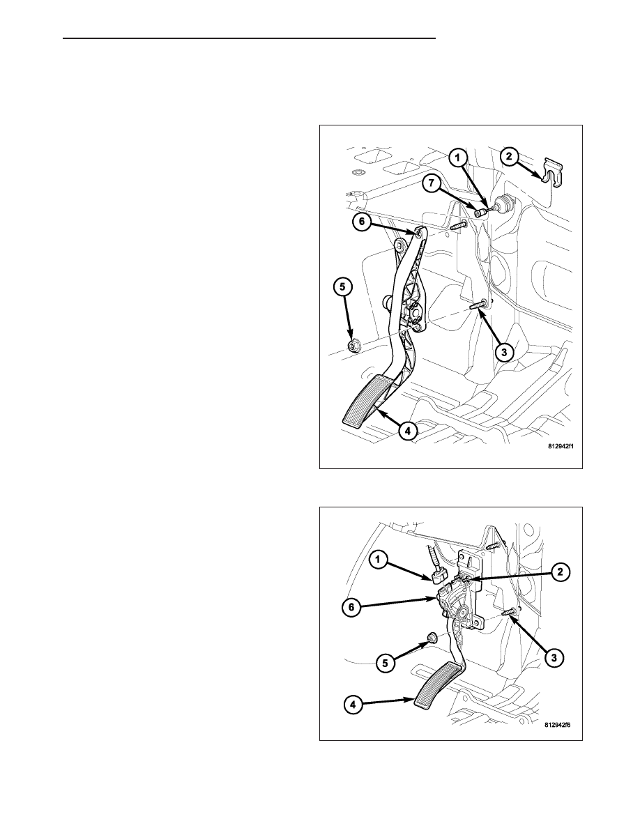
INSTALLATION
Without APPS
The following procedure applies only to vehicles with-
out the Adjustable Pedal Package (code XAP). It also
applies to vehicles not equipped with an accelerator
pedal position sensor.
The accelerator pedal is serviced as a complete
assembly including the bracket.
The accelerator cable is connected to the upper part
of the accelerator pedal arm by a plastic retainer (clip)
(7). This plastic retainer snaps into the top of the
accelerator pedal arm.
1. Place accelerator pedal assembly (4) over two
mounting studs (3).
2. Install and tighten two mounting nuts (5). Refer to
Torque Specifications.
3. Slide throttle cable into opening slot (6) in top of
pedal arm.
4. Push plastic cable retainer (clip) (7) into accelera-
tor pedal arm opening until it snaps into place.
5. Before starting engine, operate accelerator pedal to
check for any binding.
With APPS
The following procedure applies only to vehicles with-
out the Adjustable Pedal Package (code XAP). It also
applies to vehicles equipped with an accelerator
pedal position sensor (6).
The accelerator pedal is serviced as a complete
assembly including the bracket.
1. Place accelerator pedal assembly (4) over two
mounting studs (3).
2. Install and tighten two mounting nuts (5). Refer to
Torque Specifications.
3. Install electrical connector (1) to APPS (6).
4. A Scan Tool may be used to learn electrical param-
eters. Go to the Miscellaneous menu, and then
select ETC Learn.
5. If the previous step is not performed, a Diagnostic
Trouble Code (DTC) will be set.
6. If necessary, use a scan tool to erase any Diag-
nostic Trouble Codes (DTC’s) from PCM.
7. Before starting engine, operate accelerator pedal to check for any binding.
HB
FUEL INJECTION
14 - 27