Dodge Durango (HB). Manual - part 1122


  Index      Dodge     Dodge Durango (HB) - service repair manual 2005 year


Search            


Content   ..  1120  1121  1122  1123   ..


Dodge Durango (HB). Manual - part 1122


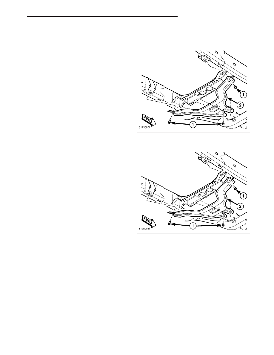
SKID PLATE-TRANSFER CASE

REMOVAL

1. Remove the bolts (1) and remove the skid plate

(2).

INSTALLATION

1. Position the skid plate (2) on the vehicle.

2. Install the bolts (1) and tighten to 23 N·m (17 ft.

lbs.).

HB

FRAME & BUMPERS

13 - 27

FUEL SYSTEM

TABLE OF CONTENTS

page

page

FUEL DELIVERY

. . . . . . . . . . . . . . . . . . . . . . . . . . 1

FUEL INJECTION

. . . . . . . . . . . . . . . . . . . . . . . . 25

FUEL DELIVERY

TABLE OF CONTENTS

page

page

FUEL DELIVERY

STANDARD PROCEDURE - FUEL SYSTEM

PRESSURE RELEASE

. . . . . . . . . . . . . . . . . . . 1

SPECIFICATIONS

FUEL SYSTEM PRESSURE

. . . . . . . . . . . . . . 2

TORQUE - FUEL SYSTEM

. . . . . . . . . . . . . . . 2

SPECIAL TOOLS

FUEL SYSTEM

. . . . . . . . . . . . . . . . . . . . . . . . 4

SENSOR-FUEL LEVEL SENDING UNIT

DESCRIPTION

. . . . . . . . . . . . . . . . . . . . . . . . . . 5

LINES, FUEL

DESCRIPTION

. . . . . . . . . . . . . . . . . . . . . . . . . . 5

FITTING, QUICK CONNECT

DESCRIPTION

. . . . . . . . . . . . . . . . . . . . . . . . . . 5

STANDARD PROCEDURE - QUICK-CONNECT

FITTINGS

. . . . . . . . . . . . . . . . . . . . . . . . . . . . 5

PUMP-FUEL

DESCRIPTION

. . . . . . . . . . . . . . . . . . . . . . . . . 11

MODULE-FUEL PUMP

DESCRIPTION

. . . . . . . . . . . . . . . . . . . . . . . . . 11

REMOVAL

. . . . . . . . . . . . . . . . . . . . . . . . . . . . . 12

INSTALLATION

. . . . . . . . . . . . . . . . . . . . . . . . . 13

RAIL-FUEL

DESCRIPTION

. . . . . . . . . . . . . . . . . . . . . . . . . 13

OPERATION

. . . . . . . . . . . . . . . . . . . . . . . . . . . 13

REMOVAL

. . . . . . . . . . . . . . . . . . . . . . . . . . . . . 14

INSTALLATION

. . . . . . . . . . . . . . . . . . . . . . . . . 19

TANK-FUEL

DESCRIPTION

. . . . . . . . . . . . . . . . . . . . . . . . . 20

REMOVAL

. . . . . . . . . . . . . . . . . . . . . . . . . . . . . 21

INSTALLATION

. . . . . . . . . . . . . . . . . . . . . . . . . 24

FILTER-INLET

DESCRIPTION

. . . . . . . . . . . . . . . . . . . . . . . . . 24

REGULATOR-FUEL PRESSURE

DESCRIPTION

. . . . . . . . . . . . . . . . . . . . . . . . . 24

FILTER-FUEL

DESCRIPTION

. . . . . . . . . . . . . . . . . . . . . . . . . 24

FUEL DELIVERY

STANDARD PROCEDURE - FUEL SYSTEM PRESSURE RELEASE

Use following procedure if the fuel injector rail is, or is not equipped with a fuel pressure test port.

1. Remove fuel fill cap.

2. Remove fuel pump relay from Power Distribution Center (PDC). For location of relay, refer to label on underside

of PDC cover.

3. Start and run engine until it stalls.

4. Attempt restarting engine until it will no longer run.

5. Turn ignition key to OFF position.

HB

FUEL SYSTEM

14 - 1

CAUTION: Steps 1, 2, 3 and 4 must be performed to relieve high pressure fuel from within fuel rail. Do not
attempt to use following steps to relieve this pressure as excessive fuel will be forced into a cylinder cham-
ber.

6. Unplug connector from any fuel injector.

7. Attach one end of a jumper wire with alligator clips (18 gauge or smaller) to either injector terminal.

8. Connect other end of jumper wire to positive side of battery.

9. Connect one end of a second jumper wire to remaining injector terminal.

CAUTION: Powering an injector for more than a few seconds will permanently damage the injector.

10. Momentarily touch other end of jumper wire to negative terminal of battery for no more than a few seconds.

11. Place a rag or towel below fuel line quick-connect fitting at fuel rail.

12. Disconnect quick-connect fitting at fuel rail. Refer to Quick-Connect Fittings.

13. Return fuel pump relay to PDC.

14. One or more Diagnostic Trouble Codes (DTC’s) may have been stored in PCM memory due to fuel pump relay

removal. A diagnostic scan tool must be used to erase a DTC.

SPECIFICATIONS

FUEL SYSTEM PRESSURE

58 psi +/- 2 psi

TORQUE - FUEL SYSTEM

DESCRIPTION

N-m

Ft. Lbs.

In. Lbs.

Accelerator Pedal Bracket

Mounting

12

-

105

Accelerator Pedal Position

Sensor Mounting Nuts -

5.7L

3

-

30

Crankshaft Position

Sensor - 3.7L

28

21

-

Crankshaft Position

Sensor - 4.7L

28

21

-

Crankshaft Position

Sensor - 5.7L

12

-

105 (+/-20)

Camshaft Position Sensor

- 3.7L

12

-

106

Camshaft Position Sensor

- 4.7L

12

-

106

Camshaft Position Sensor

- 5.7L

12

9

105 (+/-) 20

Engine Coolant

Temperature Sensor - 3.7L

11

-

96

Engine Coolant

Temperature Sensor - 4.7L

11

-

96

14 - 2

FUEL DELIVERY

HB


Content   ..  1120  1121  1122  1123   ..