Dodge Durango (HB). Manual - part 1105


  Index      Dodge     Dodge Durango (HB) - service repair manual 2005 year


Search            


Content   ..  1103  1104  1105  1106   ..


Dodge Durango (HB). Manual - part 1105


PISTON RING SPECIFICATION CHART

Ring Position

Ring/Groove

Maximum

Side Clearance

Clearance

Upper Ring

0.02-0.07mm

0.11mm

(0.0008- 0.0028 in.)

(0.004 in.)

Intermediate Ring

0.02-0.06 mm

0.10mm

(0.0008-0.0023 in.)

(0.004 in.)

Ring Position

Ring Gap

Wear Limit

Upper Ring

0.23-0.38mm

0.43mm

(0.0090-0.0149 in.)

(0.017 in.)

Intermediate Ring

0.35-0.60mm

0.74mm

(0.0137-0.0236 in.)

(0.029 in.)

Oil Control Ring

0.015-0.66mm

0.76mm

(Steel Rail)

(0.0059- 0.0259 in.)

(0.030 in.)

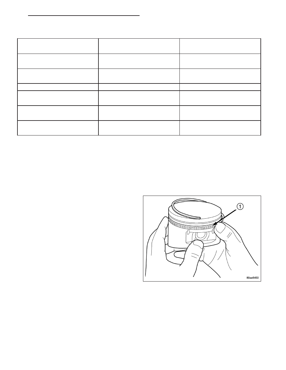
7. The No. 1 and No. 2 piston rings have a different cross section. Ensure No. 2 ring is installed with manufacturers

I.D. mark (Dot) facing up, towards top of the piston.

NOTE: Piston rings are installed in the following order:

Oil ring expander.

Lower oil ring side rail.

Upper oil ring side rail.

No. 2 Intermediate piston ring.

No. 1 Upper piston ring.

8. Install the oil ring expander.

9. Install upper side rail by placing one end between

the piston ring groove and the expander ring. Hold
end firmly and press down the portion to be
installed until side rail is in position. Repeat this
step for the lower side rail.

HB

ENGINE - 5.7L SERVICE INFORMATION

9 - 1419

10. Install No. 2 intermediate piston ring using a pis-

ton ring installer.

11. Install No. 1 upper piston ring using a piston ring

installer.

12. Position piston ring end gaps as shown in. It is

important that expander ring gap is at least 45°
from the side rail gaps, but not on the piston pin
center or on the thrust direction.

DAMPER-CRANKSHAFT

REMOVAL

1. Disconnect negative cable from battery.

2. Remove accessory drive belt (Refer to 7 - COOLING/ACCESSORY DRIVE/DRIVE BELTS - REMOVAL).

3. Drain cooling system (Refer to 7 - COOLING - STANDARD PROCEDURE).

4. Remove radiator upper hose.

5. Remove fan shroud (Refer to 7 - COOLING/ENGINE/RADIATOR FAN - REMOVAL).

6. Remove crankshaft damper bolt.

9 - 1420

ENGINE - 5.7L SERVICE INFORMATION

HB

7. Remove damper using Special Tools 8513A Insert

and 1023 Three Jaw Puller.

INSTALLATION

CAUTION: To prevent severe damage to the Crankshaft, Damper or Special Tool 8512–A, thoroughly clean
the damper bore and the crankshaft nose before installing Damper.

1. Slide damper onto crankshaft slightly.

CAUTION: Special Tool 8512–A, is assembled in a
specific sequence. Failure to assemble this tool in
this sequence can result in tool failure and severe
damage to either the tool or the crankshaft.

2. Assemble Special Tool 8512–A as follows, The nut

is threaded onto the shaft first. Then the roller
bearing is placed onto the threaded rod (The hard-
ened bearing surface of the bearing MUSTface the
nut). Then the hardened washer slides onto the
threaded rod. Once assembled coat the threaded
rod’s threads with Mopar

T

Nickel Anti-Seize or

(Loctite No. 771).

3. Using Special Tool 8512–A, press damper onto crankshaft.

4. Install then tighten crankshaft damper bolt to 176 N·m (129 ft. lbs.).

5. Install fan blade assembly (Refer to 7 - COOLING/ENGINE/FAN DRIVE VISCOUS CLUTCH - INSTALLATION).

6. Install radiator upper shroud and tighten fasteners to 11 N·m (95 in. lbs.).

7. Install radiator upper hose.

8. Install accessory drive belt (Refer to 7 - COOLING/ACCESSORY DRIVE/DRIVE BELTS - INSTALLATION).

9. Refill cooling system (Refer to 7 - COOLING - STANDARD PROCEDURE).

10. Connect negative cable to battery.

HB

ENGINE - 5.7L SERVICE INFORMATION

9 - 1421

COVER-STRUCTURAL

DESCRIPTION

The structural dust cover is made of die cast aluminum and joins the lower half of the transmission bell housing to
the engine.

OPERATION

The structural cover provides additional powertrain stiffness and reduces noise and vibration.

REMOVAL

1. Raise vehicle on hoist.

2. Remove the bolts retaining structural cover (1).

3. Remove transmission mount to crossmember fas-

teners.

4. Using suitable jack, lift transmission enough to gain

clearance for structural cover removal.

5. Remove the structural cover.

INSTALLATION

CAUTION: The structural cover must be installed as described in the following steps. Failure to do so will
cause severe damage to the cover.

1. Position the structural cover in the vehicle.

2. Install all four bolts retaining the cover-to-engine. DO NOT tighten the bolts at this time.

3. Install the four cover-to-transmission bolts. Do NOT tighten at this time.

CAUTION: The structural cover must be held tightly against both the engine and the transmission bell hous-
ing during tightening sequence. Failure to do so may cause damage to the cover.

4. Torque the (4)structural dust cover bolts that go

into the transmission to 6-11 N·m (50-100 in.lbs.).

5. Torque the (4) structural dust cover bolts that go

into the engine block to 6-11 N·m (50-100 in.lbs.).

6. Starting with the two rear cover-to-engine bolts,

tighten bolts (1) to 54 N·m (40 ft. lbs.), then tighten
bolts (2) and (3) to 54 N·m ( 40 ft. lbs.) in the
sequence shown.

7. Lower

transmission

onto

crossmember,

and

remove jack.

8. Install transmission mount to crossmember fasten-

ers, and torque (Refer to 9 - ENGINE/ENGINE
MOUNTING/REAR MOUNT - INSTALLATION).

9. Install the exhaust pipe on left hand exhaust man-

ifold, if removed.

9 - 1422

ENGINE - 5.7L SERVICE INFORMATION

HB


Content   ..  1103  1104  1105  1106   ..