Dodge Durango (HB). Manual - part 1073


  Index      Dodge     Dodge Durango (HB) - service repair manual 2005 year


Search            


Content   ..  1071  1072  1073  1074   ..


Dodge Durango (HB). Manual - part 1073


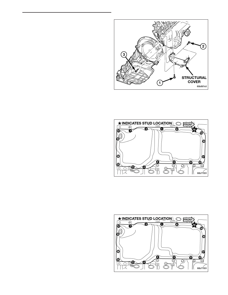
2. Remove the structural dust cover (Refer to 9 -

ENGINE/ENGINE BLOCK/STRUCTURAL COVER -
REMOVAL) using sequence shown.

3. Drain the engine oil and remove oil filter.

NOTE: Do not pry on oil pan or oil pan gasket. Gasket is mounted to engine and does not come out with oil
pan.

4. Remove the oil pan mounting bolts and oil pan.

5. Unbolt oil pump pickup tube and remove tube and oil pan gasket from engine.

INSTALLATION

INSTALLATION - 4X2

1. Clean the oil pan gasket mating surface of the bed-

plate and oil pan.

2. Position the oil pan gasket and pickup tube with

new o-ring. Install the mounting bolt and nuts.
Tighten bolt and nuts to 28 N·m (20 ft. lbs.).

3. Position the oil pan and install the mounting bolts.

Tighten the mounting bolts to 15 N·m (11 ft. lbs.) in
the sequence shown.

4. Raise the engine and remove the blocks of wood.

5. Lower engine and install both the left and right side

engine mount through bolts. Tighten the nuts to 68
N·m (50 ft. lbs.).

6. Remove jack and install oil filter.

HB

ENGINE - 4.7L SERVICE INFORMATION

9 - 1291

7. Install structural dust cover (Refer to 9 - ENGINE/

ENGINE BLOCK/STRUCTURAL COVER - INSTAL-
LATION).

8. Install exhaust pipe onto exhaust manifolds.

9. Lower vehicle.

10. Install intake manifold (Refer to 9 - ENGINE/MAN-

IFOLDS/INTAKE MANIFOLD - INSTALLATION).

11. Install throttle body resonator and air inlet hose.

12. Install upper fan shroud.

13. Fill cooling system (Refer to 7 - COOLING -

STANDARD PROCEDURE).

14. Fill engine oil.

15. Start engine and check for leaks.

INSTALLATION - 4X4

1. Clean the oil pan gasket mating surface of the bed-

plate and oil pan.

2. Position the oil pan gasket and pickup tube with

new o-ring. Install the mounting bolt and nuts.
Tighten bolt and nuts to 28 N·m (20 ft. lbs.).

3. Position the oil pan and install the mounting bolts.

Tighten the mounting bolts to 15 N·m (11 ft. lbs.) in
the sequence shown.

4. Install structural dust cover (Refer to 9 - ENGINE/

ENGINE BLOCK/STRUCTURAL COVER - INSTAL-
LATION).

5. Install oil filter.

6. Install front axle. Refer to DIFFERENTIAL AND

DRIVELINE.

7. Lower vehicle.

8. Fill engine oil.

9. Start engine check for leaks.

9 - 1292

ENGINE - 4.7L SERVICE INFORMATION

HB

SWITCH - OIL PRESSURE

DESCRIPTION

The 3–wire, electrical/mechanical engine oil pressure sensor (sending unit) is located in an engine oil pressure
gallery.

OPERATION

The oil pressure sensor uses two circuits. They are:

A signal to the PCM relating to engine oil pressure

A sensor ground through the PCM’s sensor return

The oil pressure sensor returns a voltage signal back to the PCM relating to engine oil pressure. This signal is then
transferred (bussed) to the instrument panel on a CCD bus circuit to operate the oil pressure gauge and the check
gauges lamp. Ground for the sensor is provided by the PCM through a low-noise sensor return.

REMOVAL

1. Disconnect the negative cable from the battery.

2. Raise vehicle on hoist.

3. Remove front splash shield.

4. Disconnect oil pressure sender wire (4).

5. Remove the pressure sender (2).

INSTALLATION

1. Install oil pressure sender.

2. Connect oil pressure sender wire.

3. Install front splash shield.

4. Lower vehicle.

5. Connect the negative battery cable.

PUMP - ENGINE OIL

REMOVAL

1. Remove the oil pan and pick-up tube (Refer to 9 - ENGINE/LUBRICATION/OIL PAN - REMOVAL).

2. Remove the timing chain cover (Refer to 9 - ENGINE/VALVE TIMING/TIMING BELT / CHAIN COVER(S) -

REMOVAL).

HB

ENGINE - 4.7L SERVICE INFORMATION

9 - 1293

3. Remove the timing chains and tensioners (Refer to 9 - ENGINE/VALVE TIMING/TIMING BELT/CHAIN AND

SPROCKETS - REMOVAL).

4. Remove the four bolts, primary timing chain tensioner and the oil pump.

DISASSEMBLY

1. Remove oil pump cover screws and lift off cover plate.

2. Remove pump inner and outer rotors.

NOTE: Once the oil pressure relief valve, cup plug, and pin are removed, the pump assembly must be
replaced.

3. If it is necessary to remove the pressure relief valve, drive the roll pin from pump housing and remove cup plug,

spring and valve.

CLEANING

1. Wash all parts in a suitable solvent.

INSPECTION

CAUTION: Oil pump pressure relief valve and
spring should not be removed from the oil pump.
If these components are disassembled and or
removed from the pump the entire oil pump
assembly must be replaced.

1. Clean all parts thoroughly. Mating surface of the oil

pump housing should be smooth. If the pump cover
is scratched or grooved the oil pump assembly
should be replaced.

2. Lay a straight edge across the pump cover surface

(3). If a 0.025 mm (0.001 in.) feeler gauge (2) can
be inserted between the cover and the straight
edge the oil pump assembly should be replaced.

3. Measure the thickness of the outer rotor. If the

outer rotor thickness measures at 12.005 mm
(0.472 in.) or less the oil pump assembly must be
replaced.

4. Measure the diameter of the outer rotor. If the outer

rotor diameter measures at 85.925 mm (3.382 in.)
or less the oil pump assembly must be replaced.

9 - 1294

ENGINE - 4.7L SERVICE INFORMATION

HB


Content   ..  1071  1072  1073  1074   ..