Dodge Durango (HB). Manual - part 1071


  Index      Dodge     Dodge Durango (HB) - service repair manual 2005 year


Search            


Content   ..  1069  1070  1071  1072   ..


Dodge Durango (HB). Manual - part 1071


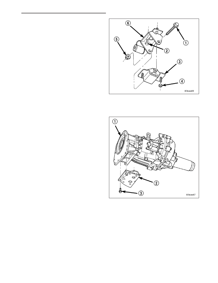
5. Raise the transmission enough to remove the

through bolt (Manual transmission and 4x2 auto-
matic transmission only).

6. Raise the transmission and remove the bolts retaining the mount to the crossmember (4x4 automatic transmis-

sion only).

7. Remove the two nuts retaining the isolator to the

crossmember (Manual transmission and 4x2 auto-
matic transmission only).

8. Remove the bolts (two bolts manual transmission-

)(three bolts 4x2 automatic transmission) retaining
the insulator bracket to the transmission.

INSTALLATION

1. Follow the removal procedure in the reverse order.

2. Tighten the through bolt retaining nut to 101 N·m (75 ft. lbs.).

3. Tighten the isolator bracket to transmission retaining bolts (Manual transmission and 4x2 automatic transmission

only) to 68 N·m (50 ft. lbs.).

4. Tighten the mount bracket to transmission retaining bolts (4x4 automatic transmission only) to 68 N·m (50 ft.

lbs.).

5. Tighten the isolator mount to crossmember retaining nuts (Manual transmission and 4x2 automatic transmission

only) to 41 N·m (30 ft. lbs.).

6. Tighten the mount bracket to crossmember retaining bolts (4x4 automatic transmission only) to 28 N·m (250 in.

lbs.).

HB

ENGINE - 4.7L SERVICE INFORMATION

9 - 1283

LUBRICATION

DESCRIPTION

The lubrication system is a full flow filtration pressure feed type.

OPERATION

Oil from the oil pan is pumped by a gerotor type oil pump directly mounted to the crankshaft nose. Oil pressure is
controlled by a relief valve mounted inside the oil pump housing.

The camshaft exhaust valve lobes and rocker arms are lubricated through a small hole in the rocker arm; oil flows
through the lash adjuster then through the rocker arm and onto the camshaft lobe. Due to the orentation of the
rocker arm, the camshaft intake lobes are not lubed in the same manner as the exhaust lobes. The intake lobes are
lubed through internal passages in the camshaft. Oil flows through a bore in the number 3 camshaft bearing bore,
and as the camshaft turns, a hole in the camshaft aligns with the hole in the camshaft bore allowing engine oil to

9 - 1284

ENGINE - 4.7L SERVICE INFORMATION

HB

enter the camshaft tube. The oil then exits through 1.6mm (0.063 in.) holes drilled into the intake lobes, lubricating
the lobes and the rocker arms.

Engine Lubrication Flow Chart—Block: Table 1

FROM

TO

Oil Pickup Tube

Oil Pump

Oil Pump

Oil Filter

Oil Filter

Block Main Oil Gallery

Block Main Oil Gallery

1. Crankshaft Main Journal

2. Left Cylinder Head*

3. Right Cylinder Head*

Crankshaft Main Journals

Crankshaft Rod Journals

Crankshaft Number One Main Journal

1.Front Timing Chain Idler Shaft

2.Both Secondary Chain Tensioners

Left Cylinder Head

See Table 2

Right Cylinder Head

See Table 2

* The cylinder head gaskets have an oil restricter to control oil flow to the cylinder heads.

Engine Lubrication Flow Chart—Cylinder Heads: Table 2

FROM

TO

Cylinder Head Oil Port (in bolt hole)

Diagonal Cross Drilling to Main Oil Gallery

Main Oil Gallery (drilled through head from rear to front)

1. Base of Camshaft Towers

2. Lash Adjuster Towers

Base of Camshaft Towers

Vertical Drilling Through Tower to Camshaft Bearings**

Lash Adjuster Towers

Diagonal Drillings to Hydraulic Lash Adjuster Pockets

** The number three camshaft bearing journal feeds oil into the hollow camshaft tubes. Oil is routed to the intake

lobes, which have oil passages drilled into them to lubricate the rocker arms.

HB

ENGINE - 4.7L SERVICE INFORMATION

9 - 1285

DIAGNOSIS AND TESTING

DIAGNOSIS AND TESTING - ENGINE OIL PRESSURE

1. Remove oil pressure sending unit and install gauge

assembly C-3292.

2. Run engine until thermostat opens.

3. Oil Pressure:

Curb Idle—25 Kpa (4 psi) minimum

3000 rpm—170 - 550 KPa (25 - 80 psi)

4. If oil pressure is 0 at idle, shut off engine. Check

for a clogged oil pick-up screen or a pressure relief
valve stuck open.

DIAGNOSIS AND TESTING - ENGINE OIL LEAK

Begin with a thorough visual inspection of the engine, particularly at the area of the suspected leak. If an oil leak
source is not readily identifiable, the following steps should be followed:

1. Do not clean or degrease the engine at this time because some solvents may cause rubber to swell, temporarily

stopping the leak.

2. Add an oil soluble dye (use as recommended by manufacturer). Start the engine and let idle for approximately 15

minutes. Check the oil dipstick to make sure the dye is thoroughly mixed as indicated with a bright yellow color
under a black light.

3. Using a black light, inspect the entire engine for fluorescent dye, particularly at the suspected area of oil leak. If

the oil leak is found and identified, repair per service manual instructions.

4. If dye is not observed, drive the vehicle at various speeds for approximately 24 km (15 miles), and repeat inspec-

tion.If the oil leak source is not positively identified at this time, proceed with the air leak detection test method.

Air Leak Detection Test Method

1. Disconnect the breather cap to air cleaner hose at the breather cap end. Cap or plug breather cap nipple.

2. Remove the PCV valve from the cylinder head cover. Cap or plug the PCV valve grommet.

3. Attach an air hose with pressure gauge and regulator to the dipstick tube.

CAUTION: Do not subject the engine assembly to more than 20.6 kPa (3 PSI) of test pressure.

4. Gradually apply air pressure from 1 psi to 2.5 psi maximum while applying soapy water at the suspected source.

Adjust the regulator to the suitable test pressure that provide the best bubbles which will pinpoint the leak
source. If the oil leak is detected and identified, repair per service manual procedures.

5. If the leakage occurs at the rear oil seal area, refer to the section, Inspection for Rear Seal Area Leak.

6. If no leaks are detected, turn off the air supply and remove the air hose and all plugs and caps. Install the PCV

valve and breather cap hose.

9 - 1286

ENGINE - 4.7L SERVICE INFORMATION

HB


Content   ..  1069  1070  1071  1072   ..