Dodge Durango (HB). Manual - part 1069


  Index      Dodge     Dodge Durango (HB) - service repair manual 2005 year


Search            


Content   ..  1067  1068  1069  1070   ..


Dodge Durango (HB). Manual - part 1069


DAMPER - CRANKSHAFT

REMOVAL

1. Disconnect negative cable from battery.

2. Remove accessory drive belt (Refer to 7 - COOL-

ING/ACCESSORY

DRIVE/DRIVE

BELTS

-

REMOVAL).

3. Drain cooling system (Refer to 7 - COOLING -

STANDARD PROCEDURE).

4. Remove radiator upper hose.

5. Remove upper fan shroud.

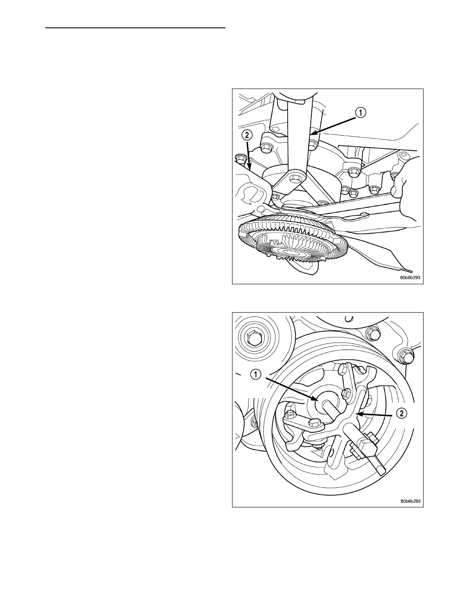
6. Using Special Tools 6958 Spanner with Adapter

Pins 8346 (1), loosen fan and viscous assembly
from water pump.

7. Remove fan and viscous assembly.

8. Disconnect electrical connector for fan mounted

inside radiator shroud.

NOTE: Transmission cooler line snaps into shroud
lower right hand corner.

9. Remove crankshaft damper bolt.

10. Remove damper using Special Tools 8513 Insert

and 1026 Three Jaw Puller (2).

HB

ENGINE - 4.7L SERVICE INFORMATION

9 - 1275

INSTALLATION

CAUTION: To prevent severe damage to the Crank-
shaft, Damper or Special Tool 8512–A, thoroughly
clean the damper bore and the crankshaft nose
before installing Damper.

1. Align crankshaft damper slot with key in crankshaft.

Slide damper onto crankshaft slightly.

CAUTION: Special Tool 8512–A, is assembled in a
specific sequence. Failure to assemble this tool in
this sequence can result in tool failure and severe
damage to either the tool or the crankshaft.

2. Assemble Special Tool 8512–A as follows, The nut

(2) is threaded onto the shaft first. Then the roller
bearing (1) is placed onto the threaded rod (3)
(The hardened bearing surface of the bearing (1)
MUSTface the nut (2). Then the hardened washer (5)slides onto the threaded rod. Once assembled coat the
threaded rod’s threads with Mopar

T

Nickel Anti-Seize or equivalent.

3. Using Special Tool 8512–A, press damper onto

crankshaft (1).

4. Install then tighten crankshaft damper bolt to 175

N·m (130 ft. lbs.).

5. Install fan blade assembly (Refer to 7 - COOLING/

ENGINE/FAN

DRIVE

VISCOUS

CLUTCH

-

INSTALLATION).

6. Install radiator upper shroud and tighten fasteners

to 11 N·m (95 in. lbs.).

7. Connect electrical connector for shroud fan.

8. Install radiator upper hose.

9. Install accessory drive belt (Refer to 7 - COOLING/

ACCESSORY DRIVE/DRIVE BELTS - INSTALLA-
TION).

10. Refill cooling system (Refer to 7 - COOLING -

STANDARD PROCEDURE).

11. Connect negative cable to battery.

9 - 1276

ENGINE - 4.7L SERVICE INFORMATION

HB

COVER - STRUCTURAL

DESCRIPTION

The structural dust cover is made of die cast aluminum and joins the lower half of the transmission bell housing to
the engine bedplate.

OPERATION

The structural cover provides additional powertrain stiffness and reduces noise and vibration.

REMOVAL

1. Raise vehicle on hoist.

2. Remove the left hand exhaust pipe from exhaust

manifold.

3. Loosen the right hand exhaust manifold-to-exhaust

pipe retaining bolts.

4. Remove the eight bolts (1,2,3) retaining structural

cover in the sequence shown.

5. Pivot the exhaust pipe downward and remove the

structural cover.

INSTALLATION

CAUTION: The structural cover must be installed
as described in the following steps. Failure to do
so will cause severe damage to the cover.

1. Position the structural cover in the vehicle.

2. Install all four bolts retaining the cover-to-engine.

DO NOT tighten the bolts at this time.

3. Install the four cover-to-transmission bolts. Do NOT

tighten at this time.

CAUTION: The structural cover must be held
tightly against both the engine and the transmis-
sion bell housing during tightening sequence. Fail-
ure to do so may cause damage to the cover.

4. Starting with the two rear cover-to-engine bolts,

tighten bolts (1) to 54 N·m (40 ft. lbs.), then tighten bolts (2) and (3) to 54 N·m ( 40 ft. lbs.) in the sequence
shown.

5. Install the exhaust pipe on left hand exhaust manifold.

6. Tighten exhaust manifold-to-exhaust pipe retaining bolts to 20–26 N·m (15–20 ft. lbs.).

HB

ENGINE - 4.7L SERVICE INFORMATION

9 - 1277

ENGINE MOUNTING

REMOVAL

2WD

1. Disconnect the negative cable from the battery.

CAUTION: Remove the viscous fan before raising engine. Failure to do so may cause damage to the fan
blade, fan clutch and fan shroud.

2. Remove the viscous fan (Refer to 7 - COOLING/ENGINE/FAN DRIVE VISCOUS CLUTCH - REMOVAL).

3. Raise the vehicle.

4. Remove the engine oil filter.

5. Remove the oil drain trough.

6. Support the engine with a suitable jack and a block of wood across the full width of the engine oil pan.

7. Support the front axle with a suitable jack.

8. Remove the (4) bolts that attach the engine mounts to the front axle.

9. Remove the (3) bolts that attach the front axle to the left engine bracket.

10. Lower the front axle.

11. Remove the through bolts

12. Raise the engine far enough to be able to remove the left and right engine mounts.

13. Remove the (8) mount to engine attaching bolts

14. Remove the engine mounts.

4WD

1. Disconnect the negative cable from the battery.

2. Remove the viscous fan.

3. Raise the vehicle.

4. Remove the skid plate.

5. Remove the front crossmember.

6. Remove the engine oil filter.

7. Remove the oil drain trough.

8. Support the engine with a suitable jack and a block of wood across the full width of the engine oil pan.

9. Support the front axle with a suitable jack.

10. Remove the (4) bolts that attach the engine mounts to the front axle.

9 - 1278

ENGINE - 4.7L SERVICE INFORMATION

HB


Content   ..  1067  1068  1069  1070   ..