Content .. 1063 1064 1065 1066 ..
Dodge Durango (HB). Manual - part 1065
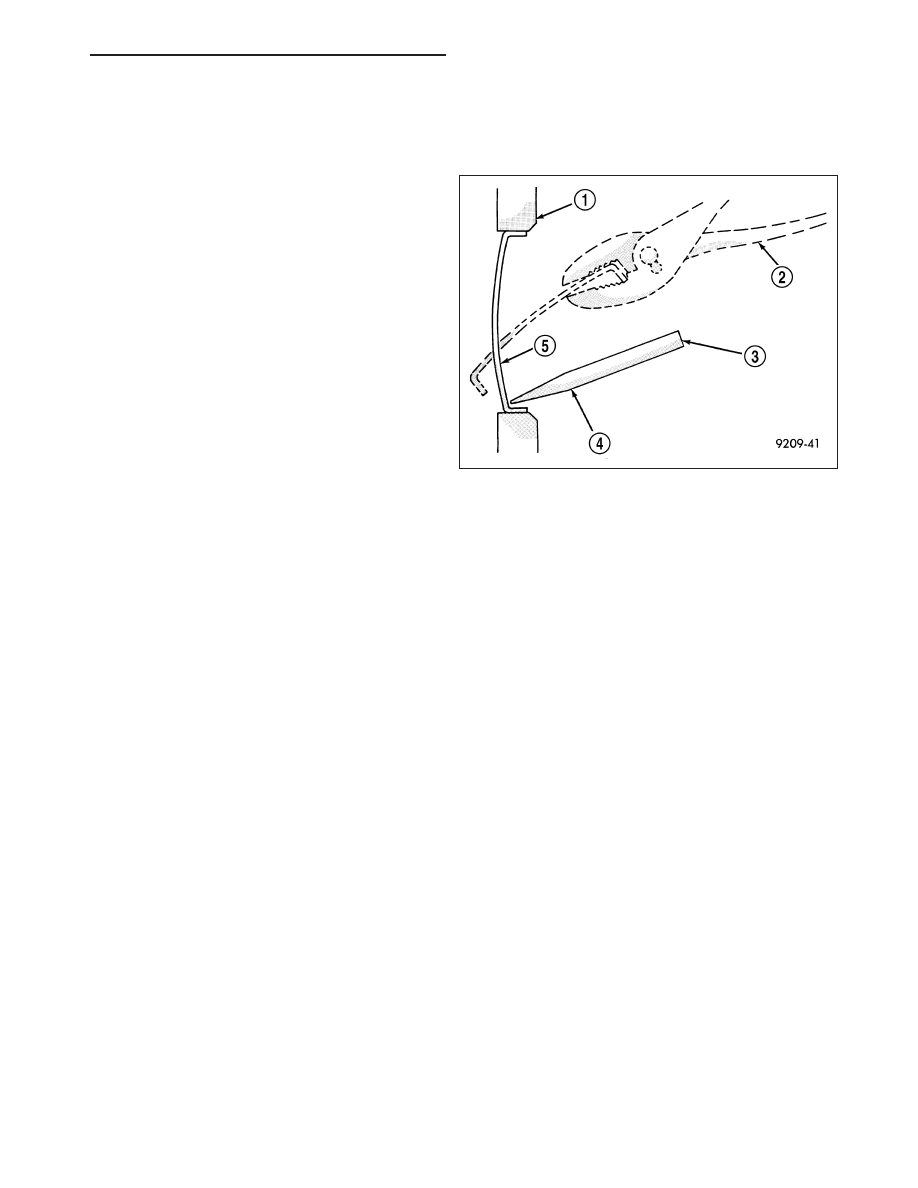
PLUGS - CORE
REMOVAL
1. Drain the cooling system (Refer to 7 - COOLING -
STANDARD PROCEDURE).
2. Using a blunt tool such as a drift or a screw driver
and a hammer, strike the bottom edge of the cup
plug (5).
3. Using a suitable pair of pliers, grasp the core plug
(2) and remove.
INSTALLATION
NOTE: Thoroughly clean core plug bore, remove all of the old sealer.
1. Coat the edges of the engine core plug and the core plug bore with Mopar Gasket Maker, or equivalent.
NOTE: It is not necessary to wait for the sealant to cure on the core plugs. The cooling system can be filled
and the vehicle returned to service immediately.
2. Using proper plug driver, drive core plug into the core plug bore. The sharp edge of the core plug should be at
least 0.50 mm (0.020 in.) inside the lead in chamfer.
3. Refill the cooling system (Refer to 7 - COOLING - STANDARD PROCEDURE).
CRANKSHAFT
DESCRIPTION
The crankshaft is constructed of nodular cast iron. The crankshaft is a crosshaped four throw design with eight
counterweights for balancing purposes. The crankshaft is supported by five select fit main bearings with the number
three serving as the thrust washer location. The main journals of the crankshaft are cross drilled to improve rod
bearing lubrication. The number eight counterweight has provisions for crankshaft position sensor target wheel
mounting. The select fit main bearing markings are located on the rear side of the target wheel. The crankshaft oil
seals are one piece design. The front oil seal is retained in the timing chain cover, and the rear seal is pressed in
to a bore formed by the cylinder block and the bedplate assembly.
REMOVAL
NOTE: To remove the crankshaft from the engine, the engine must be removed from the vehicle.
1. Remove the engine. (Refer to 9 - ENGINE - REMOVAL).
2. Remove the engine oil pump. (Refer to 9 - ENGINE/LUBRICATION/OIL PUMP - REMOVAL).
CAUTION: DO NOT pry on the oil pan gasket when removing the oil pan, The oil pan gasket is mounted to
the cylinder block in three locations and will remain attached to block when removing oil pan. Gasket can
not be removed with oil pan.
HB
ENGINE - 4.7L SERVICE INFORMATION
9 - 1259