Content .. 1003 1004 1005 1006 ..
Dodge Durango (HB). Manual - part 1005
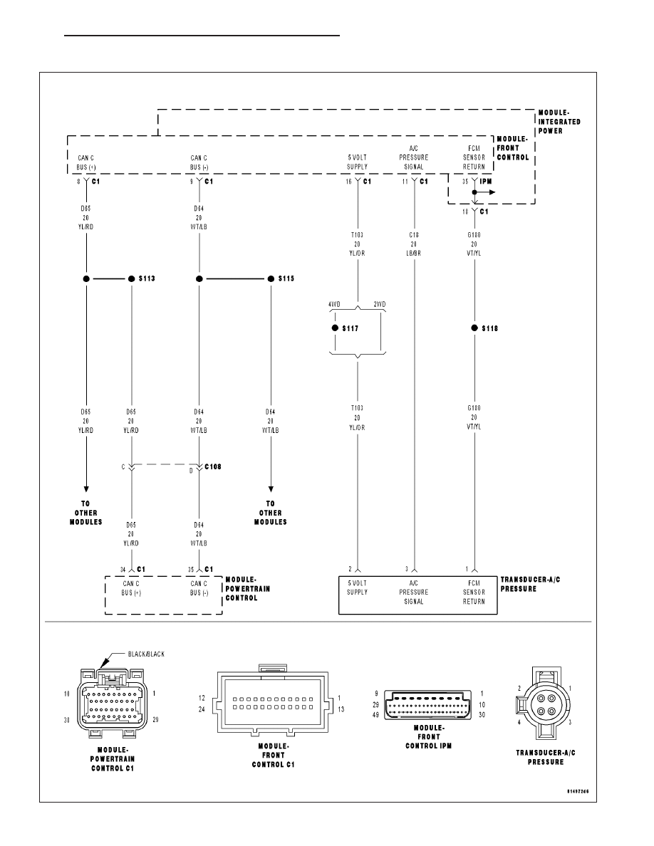
U1113-LOST A/C PRESSURE MESSAGE
HB
ENGINE ELECTRICAL DIAGNOSTICS
9 - 1019
|
|
|
Content .. 1003 1004 1005 1006 ..
U1113-LOST A/C PRESSURE MESSAGE HB ENGINE ELECTRICAL DIAGNOSTICS 9 - 1019 |