Content .. 1001 1002 1003 1004 ..
Dodge Durango (HB). Manual - part 1003
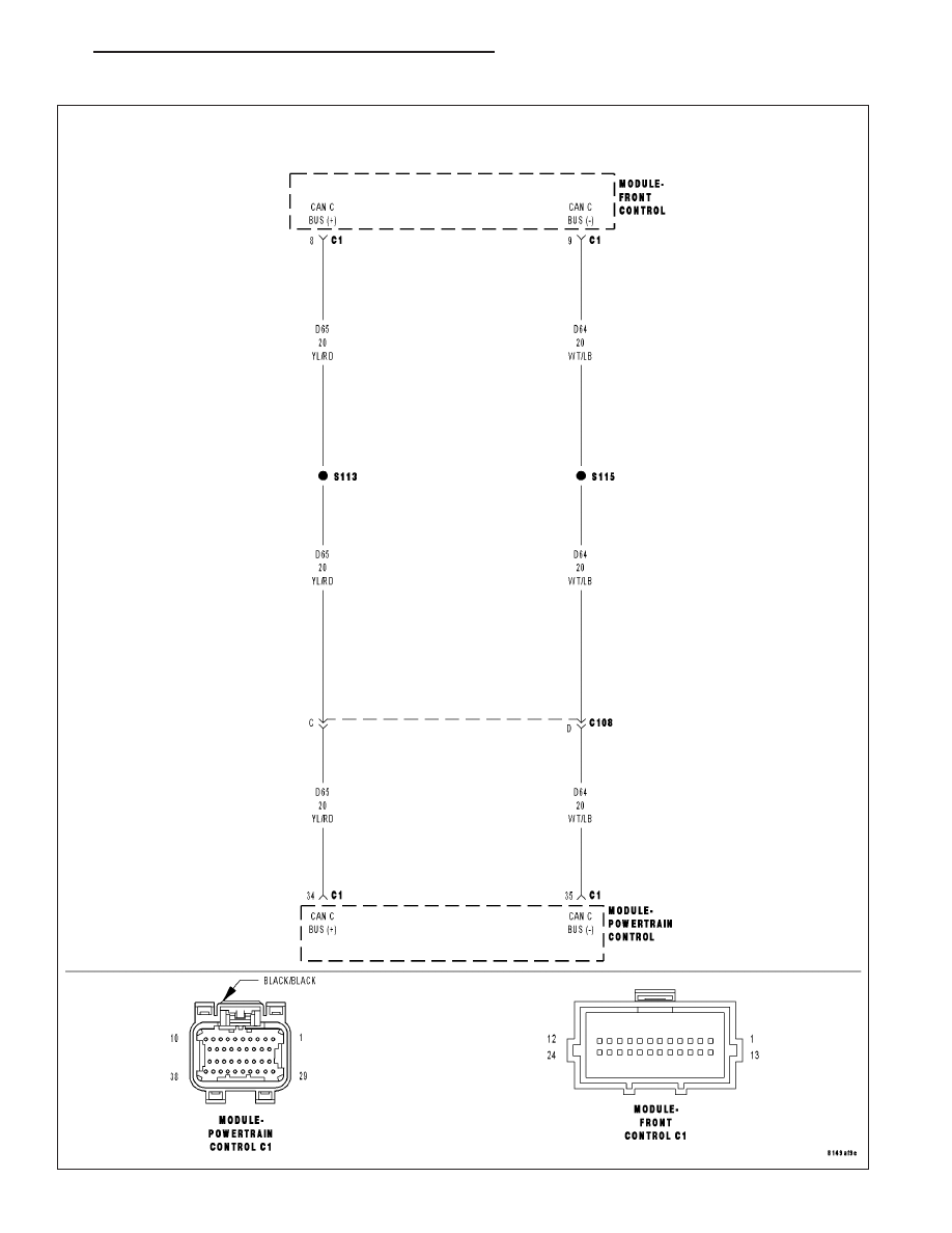
U0141-LOST COMMUNICATION WITH FRONT CONTROL MODULE
HB
ENGINE ELECTRICAL DIAGNOSTICS
9 - 1011
|
|
|
Content .. 1001 1002 1003 1004 ..
U0141-LOST COMMUNICATION WITH FRONT CONTROL MODULE HB ENGINE ELECTRICAL DIAGNOSTICS 9 - 1011 |