Dodge Durango (HB). Manual - part 62


  Index      Dodge     Dodge Durango (HB) - service repair manual 2005 year


Search            


Content   ..  60  61  62  63   ..


Dodge Durango (HB). Manual - part 62


REAR

1. Raise and support the vehicle.

2. Remove the wheel and tire assembly.

3. Drain a small amount of fluid from master cylinder

brake reservoir with a clean suction gun.

4. Bottom the caliper pistons into the caliper by prying

the caliper over.

5. Remove the caliper mounting bolts.

6. Remove the disc brake caliper from the mount.

CAUTION: Never allow the disc brake caliper to
hang from the brake hose. Damage to the brake
hose will result. Provide a suitable support to
hang the caliper securely.

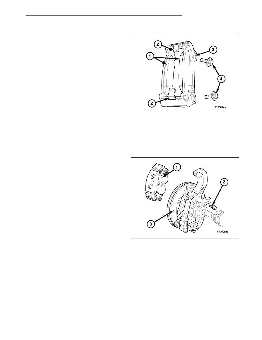
7. Remove the inboard and outboard brake pads (1).

8. Remove the anti-rattle clips (2).

9. Remove the caliper adapter mounting bolts (4).

INSTALLATION

FRONT

1. Install the caliper adapter (1) to the steering

knuckle.

2. Install the caliper adapter mounting bolts (2) and

tighten to 176 N·m (130 ft.lbs.).

3. Install the disc brake caliper (1) (Refer to 5 -

BRAKES/HYDRAULIC/MECHANICAL/DISC
BRAKE CALIPERS - INSTALLATION).

4. Install the tire and wheel assembly (Refer to 22 -

TIRES/WHEELS/WHEELS - STANDARD PROCE-
DURE).

5. Remove the support and lower the vehicle.

HB

BRAKES - BASE

5 - 27

REAR

1. Install the caliper adapter mounting bolts (4).

Tighten the mounting bolts to 135 N·m (100 ft.lbs).

2. Install the anti-rattle clips (2).

3. Install the inboard and outboard pads (1).

4. Install the caliper mounting bolts.

5. Install the tire and wheel assembly.

DISC BRAKE CALIPER ADAPTER MOUNT

REMOVAL - REAR

1. Remove wheel and tire assembly.

2. Remove the disc brake caliper (3) (Refer to 5 -

BRAKES/HYDRAULIC/MECHANICAL/DISC
BRAKE CALIPERS - REMOVAL).

3. Remove the caliper adapter (2) (Refer to 5 -

BRAKES/HYDRAULIC/MECHANICAL/DISC
BRAKE CALIPER ADAPTER - REMOVAL).

4. Remove the rotor (1) (Refer to 5 - BRAKES/HY-

DRAULIC/MECHANICAL/ROTORS - REMOVAL).

5. Remove the axle shaft (1) (Refer to 3 - DIFFER-

ENTIAL & DRIVELINE/REAR AXLE - 9 1/4/AXLE
SHAFTS - REMOVAL).

5 - 28

BRAKES - BASE

HB

6. Remove the park brake shoes (1) (Refer to 5 -

BRAKES/PARKING BRAKE/SHOES - REMOVAL).

7. Remove the parking brake cable (2) from the brake

lever (1).

8. Remove the bolts (2) attaching the support plate to

the axle and remove the support plate (1).

HB

BRAKES - BASE

5 - 29

9. Remove the caliper adapter mount (1) from the

axle housing (2).

INSTALLATION

1. Install the caliper adapter mount (1) on the axle

housing (2).

2. Install support plate (1) on axle flange. Tighten

attaching bolts (2) to 115 N·m (85 ft. lbs.).

5 - 30

BRAKES - BASE

HB


Content   ..  60  61  62  63   ..