Dodge Durango (HB). Manual - part 58


  Index      Dodge     Dodge Durango (HB) - service repair manual 2005 year


Search            


Content   ..  56  57  58  59   ..


Dodge Durango (HB). Manual - part 58


DESCRIPTION

SPECIFICATION

Front Disc Brake Rotor
Max. Thickness Variation

0.010 mm (0.0004 in.)

Rear Disc Brake Rotor
Max. Thickness Variation

0.025 mm (0.001 in.)

Minimum Front Rotor Thickness

26.4 mm (1.039 in.)

Mininium Rear Rotor Thickness

28.39 mm (1.117 in)

Rear Disc Brake Caliper

1x54 mm (2.12 in)

Rear Disc Brake Rotor

350x22 mm (13.9X.87 in)

Brake Booster
Type
Gasoline Engines

Vacuum Dual Diaphragm

BRAKE LINES

STANDARD PROCEDURE

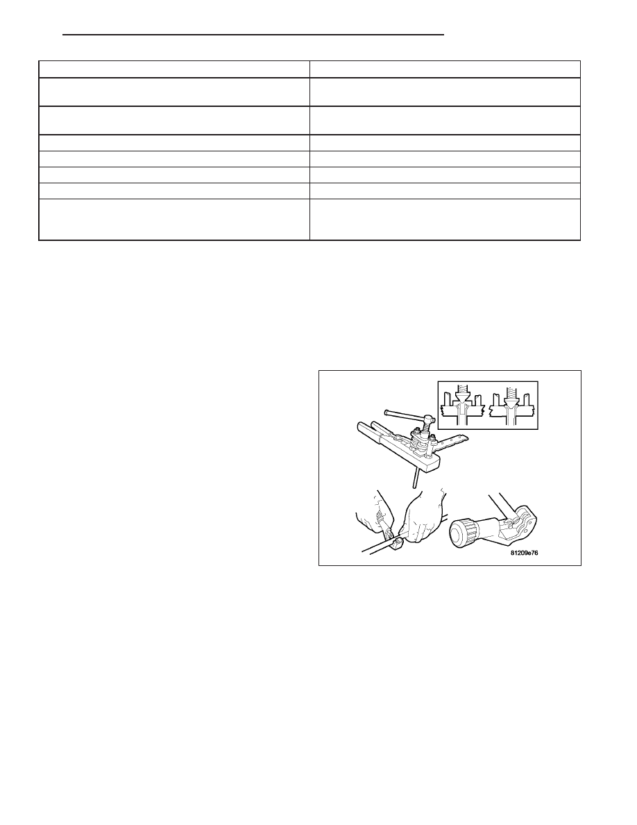
DOUBLE INVERTED FLARING

A preformed metal brake tube is recommended and preferred for all repairs. However, double-wall steel tube can be
used for emergency repair when factory replacement parts are not readily available.

1. Cut off damaged tube with Tubing Cutter.

2. Ream cut edges of tubing to ensure proper flare.

3. Install replacement tube nut on the tube.

4. Insert tube in flaring tool.

5. Place gauge form over the end of the tube.

6. Push tubing through flaring tool jaws until tube con-

tacts recessed notch in gauge that matches tube
diameter.

7. Tighten the tool bar on the tube

8. Insert plug on gauge in the tube. Then swing com-

pression disc over gauge and center tapered flaring
screw in recess of compression disc.

9. Tighten tool handle until plug gauge is squarely

seated on jaws of flaring tool. This will start the
inverted flare.

10. Remove the plug gauge and complete the inverted flare.

ISO FLARING

A preformed metal brake tube is recommended and preferred for all repairs. However, double-wall steel tube can be
used for emergency repair when factory replacement parts are not readily available.

HB

BRAKES - BASE

5 - 11

To make a ISO flare use an ISO flaring tool kit.

1. Cut off damaged tube with Tubing Cutter.

2. Remove any burrs from the inside of the tube.

3. Install tube nut on the tube.

4. Position the tube in the flaring tool flush with the

top of the tool bar (6). Then tighten the tool bar on
the tube.

5. Install the correct size adaptor (1) on the flaring

tool yoke screw.

6. Lubricate the adaptor (2).

7. Align the adaptor and yoke screw over the tube.

8. Turn the yoke screw in until the adaptor is squarely

seated on the tool bar.

REMOVAL

REAR BRAKE LINES

1. Raise and support the vehicle.

NOTE: If brake line (6) is being replaced

2. Remove the brake line (6) from the junction block

(2) at the frame, then remove the other end of the
line at the caliper hose connection.

NOTE: If brake line (1) is being replaced

3. Remove the brake line (1) from the junction block

(2) at the frame, then remove the other end of the
line at the caliper hose connection.

4. Remove the line being replaced.

5 - 12

BRAKES - BASE

HB

CALIPER HOSE ASSEMBLY

NOTE: The axle should be supported in the normal
curb position for rear brake hose change.

1. Raise and support the vehicle.

2. Remove the brake line going into the brake hose.

3. Remove the mounting bolt for the brake hose at

the frame.

4. Remove the banjo bolt (4) at the caliper (2) and

discard the copper washers (3).

5. Remove the hose (6).

FRONT HOSE

1. Raise and support vehicle.

2. Remove the tire and wheel assembly.

3. Loosen the brake line (1) from the brake hose (2)

at the frame.

4. Remove the brake line (1) from the brake hose (3)

and remove the retaining clip (2) located at the
frame.

HB

BRAKES - BASE

5 - 13

5. Remove the retaining clip from the brake hose (2).

6. Remove the brake hose banjo bolt at the caliper.

7. Remove the hose.

INSTALLATION

REAR BRAKE LINE

1. Install the line.

NOTE: If brake line (6) was replaced

2. Install the brake line (6) at the junction block (2)

located at the frame.

3. Install the brake line (6) at the brake caliper hose.

NOTE: If brake line (1) was replaced

4. Install the brake line (1) at the junction block

located at the frame.

5. Install the brake line (1) at the brake caliper hose

(6).

6. Lower the vehicle and remove the support.

7. Bleed the brake system (Refer to 5 - BRAKES -

STANDARD PROCEDURE).

5 - 14

BRAKES - BASE

HB


Content   ..  56  57  58  59   ..