Dodge Durango (DN). Manual - part 259


  Index      Dodge     Dodge Durango (DN) - service repair manual 2000 year


Search            


Content   ..  257  258  259  260   ..


Dodge Durango (DN). Manual - part 259


(5) Install lower radiator hose on thermostat hous-

ing.

(6) Install splash shield.
(7) Lower vehicle.
(8) Fill cooling system. Refer to Refilling Cooling

System in this section.

(9) Connect negative battery cable to battery.
(10) Start and warm the engine. Check for leaks.

RADIATOR

REMOVAL

WARNING: DO NOT REMOVE CYLINDER BLOCK
DRAIN PLUGS OR LOOSEN RADIATOR DRAIN-
COCK WITH SYSTEM HOT AND UNDER PRESSURE.
SERIOUS BURNS FROM COOLANT CAN OCCUR.

(1) Disconnect battery negative cable.
(2) Drain cooling system. Refer to Draining and

Filling Cooling System in this section.

WARNING: CONSTANT TENSION HOSE CLAMPS
ARE USED ON MOST COOLING SYSTEM HOSES.
WHEN REMOVING OR INSTALLING, USE ONLY
TOOLS DESIGNED FOR SERVICING THIS TYPE OF
CLAMP, SUCH AS SPECIAL CLAMP TOOL (NUMBER
6094) (Fig. 50). SNAP-ON CLAMP TOOL (NUMBER
HPC-20) MAY BE USED FOR LARGER CLAMPS.

ALWAYS WEAR SAFETY GLASSES WHEN SERVIC-
ING CONSTANT TENSION CLAMPS.

CAUTION: A number or letter is stamped into the
tongue of constant tension clamps (Fig. 51). If
replacement is necessary, use only an original
equipment clamp with matching number or letter.

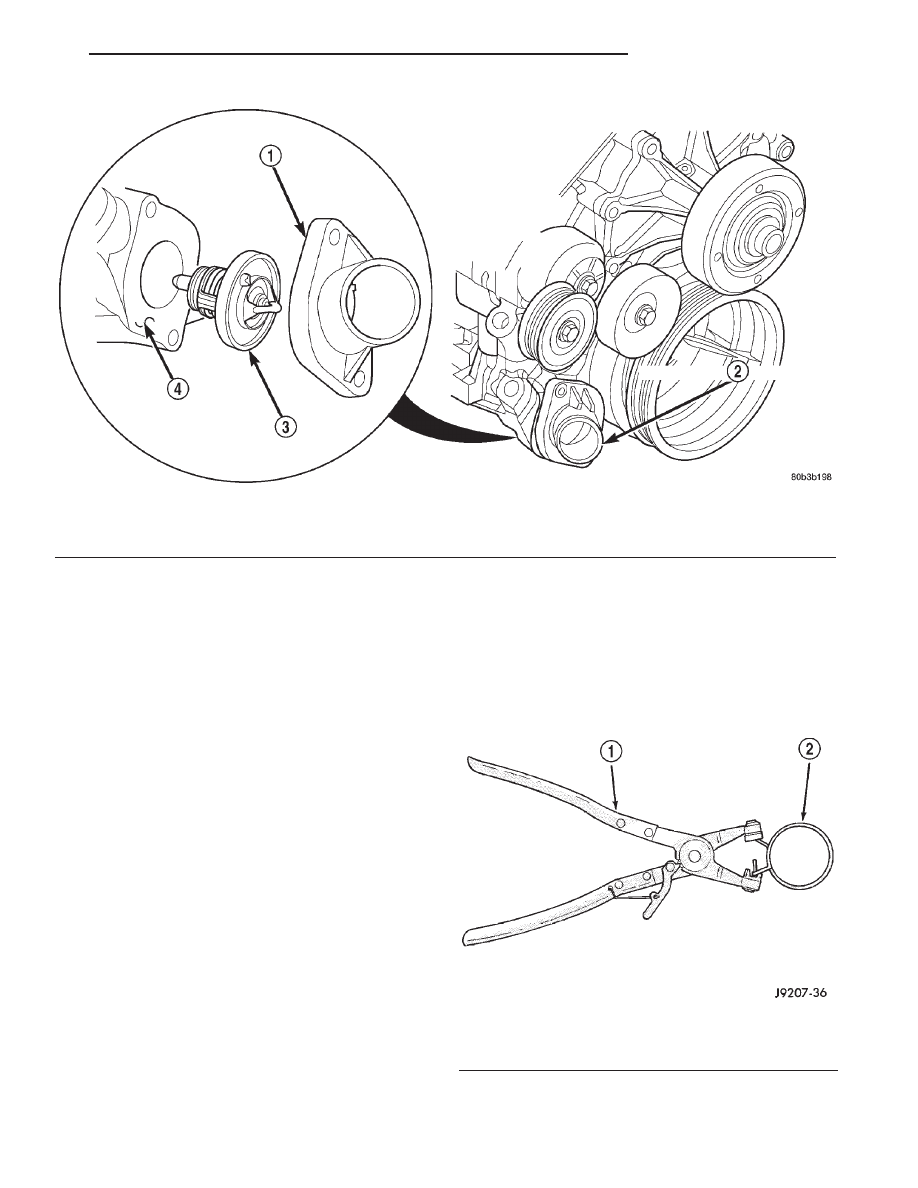
Fig. 49 Thermostat and Thermostat Housing 4.7L

1 – THERMOSTAT HOUSING
2 – THERMOSTAT LOCATION

3 – THERMOSTAT AND GASKET
4 – TIMING CHAIN COVER

Fig. 50 Hose Clamp Tool—Typical

1 – HOSE CLAMP TOOL 6094
2 – HOSE CLAMP

DN

COOLING SYSTEM

7 - 35

REMOVAL AND INSTALLATION (Continued)

(3) Remove hose clamps (Fig. 50) and hoses from

radiator. Disconnect coolant reserve/overflow tank
hose and washer bottle electrical connector and hose.

(4) Remove upper fan shroud mounting screws Lift

upper fan shroud assembly up and out of engine com-
partment (Fig. 52).

(5) Remove front grille. Refer to BODY for proce-

dure.

(6) Disconnect transmission oil cooler lines, (if

equipped) (Fig. 53).

(7) Disconnect electric cooling fan motor connector.
(8) Remove radiator upper mounting screws (Fig.

54). Lift radiator upward and away from vehicle. Do
not allow cooling fins of radiator to contact any other
vehicle component. Radiator fin damage could result.

INSTALLATION

The radiator has two isolator pins on bottom of

both tanks. These fit into alignment holes in radiator
lower support (Fig. 54).

(1) Position isolator pins into alignment holes in

radiator lower support.

(2) Install and tighten radiator mounting bolts to

23 N·m (200 in. lbs.) (Fig. 54).

(3) Install the transmission oil cooler lines, (if

equipped).

(4) Install front grille.
(5) Connect fan motor electrical connector to har-

ness connector.

(6) Position upper fan shroud onto lower fan

shroud and radiator.

(7) Install retaining screws into shroud.
(8) Install

radiator

hoses.

reconnect

coolant

reserve/overflow tank hose.

(9) Connect battery negative cable.

(10) Fill cooling system. Refer to Draining and

Filling Cooling System in this section.

(11) Start and warm the engine. Check for leaks.

Fig. 51 Clamp Number/Letter Location

1 – CONSTANT TENSION HOSE CLAMP
2 – CLAMP NUMBER/LETTER LOCATION
3 – HOSE

Fig. 52 Radiator Upper Fan Shroud Removal/

Installation—Typical

1 – RADIATOR
2 – ELECTRIC COOLING FAN
3 – UPPER SHROUD AND OVERFLOW BOTTLE
4 – SCREW
5 – LOWER SHROUD

Fig. 53 Transmission Oil Cooler Lines—Automatic

Transmission Only

1 – TRANSMISSION COOLER SUPPLY LINE
2 – TRANSMISSION OIL COOLER RETURN LINE

7 - 36

COOLING SYSTEM

DN

REMOVAL AND INSTALLATION (Continued)

BLOCK HEATER

REMOVAL

(1) Disconnect negative battery cable from battery.
(2) Drain coolant from radiator and cylinder block.

Refer to Draining Cooling System in this group.

(3) Remove power cord from block heater (Fig. 55).
(4) Loosen screw at center of block heater. Remove

heater assembly and o-ring seal.

INSTALLATION

(1) Thoroughly clean cylinder block core hole and

block heater seat.

(2) (all except 4.7L Engine). Position o-ring seal

on heater then insert block heater assembly with ele-
ment loop pointing down (Fig. 55).

(3) 4.7L Engine Only, Insert block heater assem-

bly with element loop pointing upward (12 O’clock)
(Fig. 56).

(4) With block heater fully seated, tighten center

screw to 2 N·m (17 in. lbs.) torque.

(5) Fill cooling system with recommended coolant.

Refer to Filling Cooling System section in this group.

(6) Start and warm the engine. Check for leaks.

ACCESSORY DRIVE BELT—5.2L/5.9L ENGINE

REMOVAL

Drive belts on 5.2L/5.9L engines are equipped with

a spring loaded automatic belt tensioner (Fig. 57).
This belt tensioner will be used on all belt configura-

tions, such as with or without power steering or air
conditioning. For more information, refer to Auto-
matic Belt Tensioner—5.2L/5.9L Engine, in this sec-
tion.

Fig. 54 Radiator Removal/Installation—Typical

1 – CORE SUPPORT
2 – LOWER ISOLATOR MOUNTS
3 – ISOLATOR PINS
4 – RADIATOR ASSEMBLY
5 – SCREWS

Fig. 55 Block Heater Removal/Installation—5.2L/5.9L

1 – BLOCK HEATER POWER CORD
2 – POWER CORD ROUTING CLIP (2)
3 – FREEZE PLUG
4 – O-RING SEAL
5 – BLOCK HEATER

Fig. 56 Engine Block Heater—4.7L

1 – ENGINE BLOCK HEATER

DN

COOLING SYSTEM

7 - 37

REMOVAL AND INSTALLATION (Continued)

(1) Attach a socket/wrench to pulley mounting bolt

of automatic tensioner (Fig. 57).

(2) Rotate tensioner assembly clockwise (as viewed

from front) until tension has been relieved from belt.

(3) Remove belt from idler pulley first.
(4) Remove belt from vehicle.

INSTALLATION

CAUTION: When installing serpentine accessory
drive belt, the belt must be routed correctly. If not,
engine may overheat due to water pump rotating in
wrong direction. Refer to (Fig. 58) for correct engine
belt routing. The correct belt with correct length
must be used.

(1) Position drive belt over all pulleys except idler

pulley. This pulley is located between generator and
A/C compressor.

(2) Attach a socket/wrench to pulley mounting bolt

of automatic tensioner (Fig. 57).

(3) Rotate socket/wrench clockwise. Place belt over

idler pulley. Let tensioner rotate back into place.
Remove wrench. Be sure belt is properly seated on
all pulleys.

(4) Check belt indexing marks. Refer to Automatic

Belt Tensioner—5.2L/5.9L for more belt information.

The tensioner is equipped with an indexing arrow

on back of tensioner and an indexing mark on ten-
sioner housing. If a new belt is being installed, arrow
must be within approximately 3 mm (1/8 in.) of
indexing mark. Belt is considered new if it has been
used 15 minutes or less. If this specification cannot
be met, check for:

• The wrong belt being installed (incorrect length/

width)

• Worn bearings on an engine accessory (A/C com-

pressor, power steering pump, water pump, idler pul-
ley or generator)

• A pulley on an engine accessory being loose

• Misalignment of an engine accessory

• Belt incorrectly routed. Refer to (Fig. 58)

ACCESSORY BELT REPLACEMENT—4.7L
ENGINE

NOTE: The belt routing schematics are published
from the latest information available at the time of
publication. If anything differs between these sche-
matics and the Belt Routing Label, use the sche-
matics on Belt Routing Label. This label is located
in the engine compartment.

Fig. 57 Automatic Belt Tensioner—Belt Removal/

Installation

1 – IDLER PULLEY
2 – TENSIONER
3 – FAN BLADE

Fig. 58 Belt Routing—5.2L/5.9L Engine

1 – TENSIONER
2 – GENERATOR PULLEY
3 – IDLER PULLEY
4 – A/C COMPRESSOR PULLEY
5 – WATER PUMP PULLEY
6 – POWER STEERING PUMP PULLEY
7 – CRANKSHAFT PULLEY

7 - 38

COOLING SYSTEM

DN

REMOVAL AND INSTALLATION (Continued)


Content   ..  257  258  259  260   ..