Dodge Dakota (R1). Manual - part 770


  Index      Dodge     Dodge Dakota (R1) - service repair manual 2000 year


Search            


Content   ..  768  769  770  771   ..


Dodge Dakota (R1). Manual - part 770


(5) Simultaneously lift upward and outward to

release retainer steps from inner door panel (Fig. 14).

(6) Disengage inside handle linkage rod from

inside handle.

(7) Disconnect speaker harness wire connector

(Fig. 15).

(8) Disengage clips attaching power window/lock

switch panel to door trim panel. Disengage wire con-
nector from switch panel, if equipped (Fig. 16).

(9) Separate door trim panel from vehicle.

INSTALLATION

(1) Position trim panel at door.
(2) Engage wire connector for window/lock switch

panel, if equipped. Engage clips attaching power win-
dow/lock switch panel to door trim panel.

(3) Engage

power

mirror

wire

connector,

if

equipped.

(4) Connect speaker harness wire connector.
(5) Engage inside handle linkage rod to inside

handle.

(6) Align trim panel retainer steps with inner door

panel and slide trim panel into place.

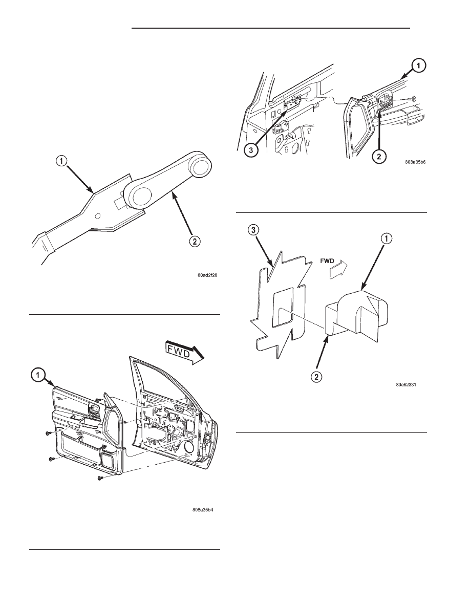
Fig. 11 Window Crank—Typical

1 - WINDOW CRANK REMOVAL TOOL
2 - WINDOW CRANK

Fig. 12 Door Trim Panel

1 - TRIM PANEL

Fig. 13 Trim Panel Screw

1 - TRIM PANEL
2 - INSIDE DOOR HANDLE
3 - INSIDE DOOR HANDLE BRACKET

Fig. 14 Trim Panel Retainer

1 - TRIM PANEL
2 - RETAINER STEP
3 - INNER DOOR PANEL

23 - 68

DOOR - FRONT

AN

TRIM PANEL (Continued)

(7) Install screws attaching trim panel to door.
(8) Install window crank, if equipped.

FRONT DOOR WATERDAM

REMOVAL

(1) Remove the trim panel from the door.
(2) Carefully separate the waterdam from the door

inner panel at the areas with adhesive (Fig. 17).
Remove the waterdam from the door inner panel.

INSTALLATION

(1) Apply an appropriate adhesive/sealant to the

waterdam edges before installing it.

(2) Position the waterdam on the door inner panel

and press it inward at the areas with the adhesive to
attach it to the inner panel.

(3) Ensure that the retainer step pockets are posi-

tion correctly in the door inner panel.

(4) Install the door trim panel.

Fig. 15 Speaker And Power Mirror Connector

1 - SPEAKER CONNECTOR

Fig. 16 Power Door Lock/Window Connector

1 - TRIM PANEL SWITCH BEZEL OPENING
2 - WIRE HARNESS CONNECTOR
3 - SWITCH AND BEZEL UNIT

Fig. 17 Water Dam

1 - STUFFERS
2 - RETAINER STEP POCKETS
3 - WATER DAM

AN

DOOR - FRONT

23 - 69

TRIM PANEL (Continued)

FRONT DOOR WINDOW
REGULATOR

REMOVAL

(1) Remove door trim panel.
(2) Remove water dam as necessary to access win-

dow regulator.

(3) Remove glass from door.
(4) Disengage power window motor wire connector

from door harness, if equipped (Fig. 18).

(5) Loosen bolts in slotted holes attaching regula-

tor to door inner panel (Fig. 19).

(6) Remove bolts attaching window regulator to

inner door panel.

(7) Extract window regulator through access hole

in inner door panel.

(8) Separate window regulator from door panel.

INSTALLATION

(1) Position regulator in door and align bolts with

slotted holes in door inner panel.

(2) Install bolts attaching window regulator to

inner door panel.

(3) Engage power window motor wire connector to

door harness, if equipped.

(4) Install glass in door.
(5) Install outer belt weatherstrip.
(6) Install inner belt weatherstrip.
(7) Install water dam.
(8) Install door trim panel.
(9) Verify operation.

Fig. 18 Power Regulator

1 - SCREW
2 - SCREW
3 - POWER WINDOW REGULATOR

Fig. 19 Power Regulator Bolts

1 - REMOVE BOLTS
2 - LOOSEN BOLTS
3 - DOOR INNER PANEL

23 - 70

DOOR - FRONT

AN

DOORS - REAR

TABLE OF CONTENTS

page

page

DOORS - REAR

REMOVAL . . . . . . . . . . . . . . . . . . . . . . . . . . . . . . 71
INSTALLATION. . . . . . . . . . . . . . . . . . . . . . . . . . . 71
ADJUSTMENTS . . . . . . . . . . . . . . . . . . . . . . . . . . 71

DOOR GLASS

REMOVAL . . . . . . . . . . . . . . . . . . . . . . . . . . . . . . 72
INSTALLATION. . . . . . . . . . . . . . . . . . . . . . . . . . . 72

REAR DOOR OUTSIDE HANDLE

REMOVAL . . . . . . . . . . . . . . . . . . . . . . . . . . . . . . 73
INSTALLATION. . . . . . . . . . . . . . . . . . . . . . . . . . . 73

REAR DOOR GLASS RUN CHANNELS

REMOVAL . . . . . . . . . . . . . . . . . . . . . . . . . . . . . . 73
INSTALLATION. . . . . . . . . . . . . . . . . . . . . . . . . . . 73

REAR DOOR HINGE

REMOVAL . . . . . . . . . . . . . . . . . . . . . . . . . . . . . . 74
INSTALLATION. . . . . . . . . . . . . . . . . . . . . . . . . . . 74

REAR DOOR INSIDE HANDLE ACTUATOR

DESCRIPTION . . . . . . . . . . . . . . . . . . . . . . . . . . . 74

REAR DOOR LATCH

REMOVAL . . . . . . . . . . . . . . . . . . . . . . . . . . . . . . 74
INSTALLATION. . . . . . . . . . . . . . . . . . . . . . . . . . . 74

REAR DOOR LATCH STRIKER

REMOVAL . . . . . . . . . . . . . . . . . . . . . . . . . . . . . . 74
INSTALLATION. . . . . . . . . . . . . . . . . . . . . . . . . . . 74

REAR DOOR TRIM PANEL

REMOVAL . . . . . . . . . . . . . . . . . . . . . . . . . . . . . . 75
INSTALLATION. . . . . . . . . . . . . . . . . . . . . . . . . . . 75

REAR DOOR WATERDAM

REMOVAL . . . . . . . . . . . . . . . . . . . . . . . . . . . . . . 75
INSTALLATION. . . . . . . . . . . . . . . . . . . . . . . . . . . 76

REAR DOOR WINDOW REGULATOR

REMOVAL . . . . . . . . . . . . . . . . . . . . . . . . . . . . . . 76
INSTALLATION. . . . . . . . . . . . . . . . . . . . . . . . . . . 76

DOORS - REAR

REMOVAL

(1) Remove B-pillar trim.
(2) Disconnect door wire harness connector.
(3) Support door on suitable stand.
(4) Using a wax crayon or equivalent, mark hinge

position on B-pillar.

(5) Remove

bolts

attaching

hinge

to

B-pillar

(Fig. 1).

INSTALLATION

(1) Align and position door on vehicle.
(2) Install bolts attaching hinge to B-pillar (Fig. 1).

Tighten bolts to 28 N·m (20 ft. lbs.) torque.

(3) Connect door wire harness connector.
(4) Install B-pillar trim.

ADJUSTMENTS

Minor adjustment for alignment of the door is

made by moving the latch striker

IN AND OUT

(1) Loosen the latch striker.
(2) Tap the latch striker inward if the door charac-

ter line is outboard of the body character line or tap
the latch striker outward if the door character line is
inboard of the body character line.

(3) Inspect alignment. If correct, tighten striker to

28 N·m (20 ft. lbs.) torque.

UP AND DOWN

(1) Loosen the latch striker.
(2) Tap the latch striker downward if the door

character line is higher than the body character line

Fig. 1 Rear Door Hinge

1 - B-PILLAR
2 - LOWER HINGE
3 - UPPER HINGE

AN

DOORS - REAR

23 - 71


Content   ..  768  769  770  771   ..