Dodge Dakota (R1). Manual - part 768


  Index      Dodge     Dodge Dakota (R1) - service repair manual 2000 year


Search            


Content   ..  766  767  768  769   ..


Dodge Dakota (R1). Manual - part 768


INSTALLATION

(1) Position latch release in tailgate.
(2) Engage latch release rods.
(3) Install screws attaching latch release handle to

tailgate.

(4) Position the top of the bezel in tailgate and

slide the bezel upward and snap into place.

TAILGATE LATCH STRIKER

REMOVAL

(1) Release tailgate latch and open tailgate.
(2) Remove tailgate check cable.
(3) Using a grease pencil, mark the location of the

striker.

(4) Remove striker from cargo box (Fig. 4).

INSTALLATION

(1) Align the striker using the reference marks.
(2) Install striker.
(3) Install tailgate check cable.

TAILGATE

REMOVAL

(1) Release tailgate latch and open tailgate.
(2) Disconnect tailgate check cable.
(3) Close tailgate until the notch in the right hand

collar aligns with the pivot pin.

(4) Slip tailgate hinge collar from hinge pins.
(5) Slide tailgate to the right and separate left

hand collar from the pivot pin.

(6) Separate tailgate from vehicle.

INSTALLATION

Reverse the preceding operation.
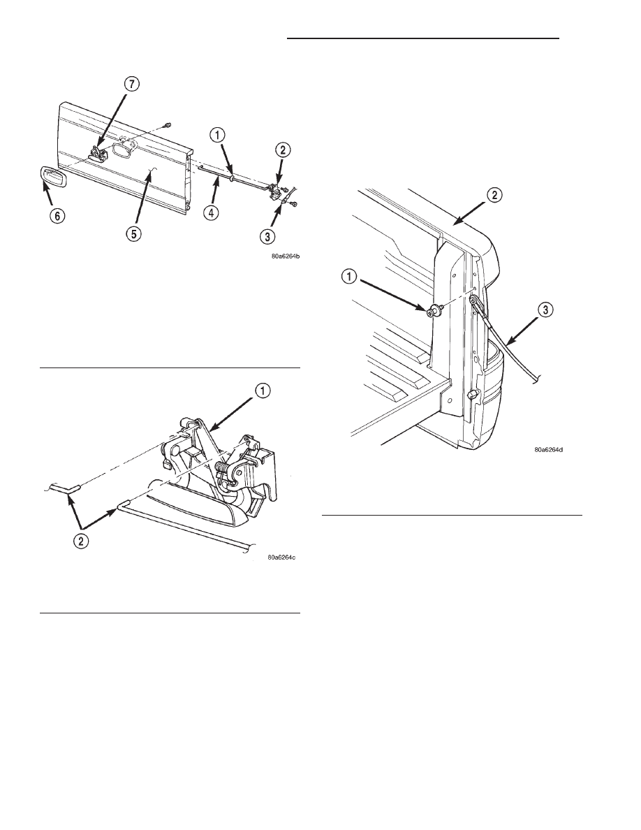
Fig. 2 Tailgate

1 - SILENCER DISC
2 - LATCH
3 - CABLE
4 - LATCH RELEASE ROD
5 - TAILGATE
6 - BEZEL
7 - LATCH RELEASE

Fig. 3 Latch Release Rods

1 - TAILGATE LATCH RELEASE
2 - TAILGATE LATCH RELEASE RODS

Fig. 4 Tailgate Latch Striker

1 - STRIKER
2 - BODY
3 - CABLE

23 - 60

DECKLID/HATCH/LIFTGATE/TAILGATE

AN

TAILGATE LATCH RELEASE HANDLE (Continued)

DOOR - CARGO

TABLE OF CONTENTS

page

page

AIR EXHAUSTER

REMOVAL . . . . . . . . . . . . . . . . . . . . . . . . . . . . . . 61

INSTALLATION. . . . . . . . . . . . . . . . . . . . . . . . . . . 61

AIR EXHAUSTER

REMOVAL

(1) Release door latch and open door.
(2) Using a small flat blade, depress the clips

under the top of the exhauster frame.

(3) Separate air exhauster from vehicle.

INSTALLATION

(1) Position air exhauster on door shut face (Fig.

1).

(2) Engage clips and press into place.

Fig. 1 Air Exhauster

1 - DOOR SHUT FACE
2 - AIR EXHAUSTER

AN

DOOR - CARGO

23 - 61

DOOR - FRONT

TABLE OF CONTENTS

page

page

FRONT DOOR

REMOVAL . . . . . . . . . . . . . . . . . . . . . . . . . . . . . . 62
INSTALLATION. . . . . . . . . . . . . . . . . . . . . . . . . . . 62
ADJUSTMENTS . . . . . . . . . . . . . . . . . . . . . . . . . . 63

FRONT DOOR GLASS

REMOVAL . . . . . . . . . . . . . . . . . . . . . . . . . . . . . . 63
INSTALLATION. . . . . . . . . . . . . . . . . . . . . . . . . . . 63

FRONT DOOR OUTSIDE HANDLE

REMOVAL . . . . . . . . . . . . . . . . . . . . . . . . . . . . . . 63
INSTALLATION. . . . . . . . . . . . . . . . . . . . . . . . . . . 64

FDR LOWER GLASS RUN CHANNELS

REMOVAL . . . . . . . . . . . . . . . . . . . . . . . . . . . . . . 64
INSTALLATION. . . . . . . . . . . . . . . . . . . . . . . . . . . 64

FRONT DOOR HINGE

DESCRIPTION . . . . . . . . . . . . . . . . . . . . . . . . . . . 65
REMOVAL . . . . . . . . . . . . . . . . . . . . . . . . . . . . . . 65
INSTALLATION. . . . . . . . . . . . . . . . . . . . . . . . . . . 65

FRONT DOOR INSIDE HANDLE ACTUATOR

DESCRIPTION . . . . . . . . . . . . . . . . . . . . . . . . . . . 65

FRONT DOOR LATCH

REMOVAL . . . . . . . . . . . . . . . . . . . . . . . . . . . . . . 65

INSTALLATION. . . . . . . . . . . . . . . . . . . . . . . . . . . 66
ADJUSTMENTS . . . . . . . . . . . . . . . . . . . . . . . . . . 66

FRONT DOOR LATCH STRIKER

REMOVAL . . . . . . . . . . . . . . . . . . . . . . . . . . . . . . 66
INSTALLATION. . . . . . . . . . . . . . . . . . . . . . . . . . . 66

FRONT DOOR LOCK CYLINDER

DESCRIPTION . . . . . . . . . . . . . . . . . . . . . . . . . . . 67
REMOVAL . . . . . . . . . . . . . . . . . . . . . . . . . . . . . . 67
INSTALLATION. . . . . . . . . . . . . . . . . . . . . . . . . . . 67

TRIM PANEL

REMOVAL . . . . . . . . . . . . . . . . . . . . . . . . . . . . . . 67
INSTALLATION. . . . . . . . . . . . . . . . . . . . . . . . . . . 68

FRONT DOOR WATERDAM

REMOVAL . . . . . . . . . . . . . . . . . . . . . . . . . . . . . . 69
INSTALLATION. . . . . . . . . . . . . . . . . . . . . . . . . . . 69

FRONT DOOR WINDOW REGULATOR

REMOVAL . . . . . . . . . . . . . . . . . . . . . . . . . . . . . . 70
INSTALLATION. . . . . . . . . . . . . . . . . . . . . . . . . . . 70

FRONT DOOR

REMOVAL

(1) Release door latch and open door.
(2) Using a suitable marker, mark the outline of

the door hinges on the door end to aid installation.

(3) Remove protective boot from door wire harness

connector.

(4) Disengage door wire harness connector.
(5) Support door on a suitable lifting device.
(6) While holding the door steady on lift, remove

bolts and nuts attaching upper and lower door hinge
to door end (Fig. 1).

(7) Separate door from vehicle.

INSTALLATION

(1) Support door on a suitable lifting device.
(2) Position door on vehicle and align with marks.
(3) Install bolts and nuts attaching upper and

lower door hinge to door end. Tighten fasteners to 28
N·m (21 ft. lbs.) torque.

(4) Engage door wire harness connector.
(5) Install protective boot on door wire harness

connector.

Fig. 1 Door Hinge

1 - UPPER HINGE
2 - LOWER HINGE
3 - DOOR
4 - STUD

23 - 62

DOOR - FRONT

AN

ADJUSTMENTS - UP/DOWN

Up/down door adjustment is done by loosening the

hinge to cowl fasteners at both hinges. Then move
the door to the correct position.

(1) Support the door with a padded floor jack.
(2) Loosen hinge to cowl fasteners at both hinges.

Move the door to the correct up/down position.

(3) Tighten the hinge to cowl fasteners.
(4) Remove the floor jack from the door.

ADJUSTMENTS - IN/OUT

In/out door adjustment is done by loosening the

hinge to door fasteners. Then move the door to the
correct position.

(1) Support the door with a padded floor jack.
(2) Loosen the applicable hinge to door fasteners.

Move the door to the correct in/out position.

(3) If necessary, loosen the other hinge to door fas-

teners and move the door to the correct in/out posi-
tion.

(4) Tighten the hinge to door fasteners.
(5) Remove the floor jack from the door.

FRONT DOOR GLASS

REMOVAL

(1) Remove door trim panel.
(2) Remove water dam as necessary to gain access

to glass regulator arm.

(3) Remove inner door belt weatherstrip.
(4) Remove outer door belt weatherstrip.
(5) Lower glass to full down position and align

glass regulator arm with access holes in inner door
panel.

(6) Remove front glass run channel.
(7) Remove nuts attaching glass channel to regula-

tor arm (Fig. 2).

(8) Separate glass from regulator arm.
(9) Lift glass upward and out of opening at top of

door.

INSTALLATION

(1) Slowly lower glass into door.
(2) Position glass in regulator arm.
(3) Install front glass run channel.
(4) Install nuts attaching glass channel to regula-

tor arm.

(5) Ensure glass is aligned in run channels and

tighten run channel bolts.

(6) Install outer door belt weatherstrip.
(7) Install inner door belt weatherstrip.
(8) Install water dam.
(9) Install door trim panel.

FRONT DOOR OUTSIDE
HANDLE

REMOVAL

(1) Remove door trim panel.
(2) Remove water dam as necessary to gain access

to door handle.

(3) Roll glass up.
(4) Remove fastener access plug from door end

panel (Fig. 3).

(5) Disengage lock cylinder to latch rod from the

latch (Fig. 4).

(6) Disengage outside handle to latch rod from the

latch.

(7) Remove nuts attaching outside door handle to

door.

(8) Separate outside handle from the door.

Fig. 2 Door Glass

1 - GLASS
2 - GLASS CHANNEL
3 - NUT
4 - REGULATOR ARM

AN

DOOR - FRONT

23 - 63

FRONT DOOR (Continued)


Content   ..  766  767  768  769   ..