Dodge Dakota (R1). Manual - part 769


  Index      Dodge     Dodge Dakota (R1) - service repair manual 2000 year


Search            


Content   ..  767  768  769  770   ..


Dodge Dakota (R1). Manual - part 769


INSTALLATION

(1) Position outside handle in the door.
(2) Install nuts attaching outside door handle to

door. Tighten the nuts to 5.0 N·m (45 in. lbs) torque.

(3) Engage outside handle to latch rod to the latch.
(4) Engage lock cylinder to latch rod to the latch.
(5) Install fastener access plug in the door end

panel.

(6) Install water dam.
(7) Install door trim panel.

FDR LOWER GLASS RUN
CHANNELS

REMOVAL

(1) Remove trim panel.
(2) Remove water dam as necessary to access

lower run channels.

(3) Remove bolts attaching lower glass run chan-

nels to door panel (Fig. 5).

(4) Remove glass.
(5) Slide lower run channels downward to disen-

gage from upper run channels.

(6) Remove lower run channels from door.

INSTALLATION

(1) Position lower run channels in door.
(2) Slide lower run channels upward to engage

into upper run channels.

(3) Install glass.
(4) Install bolts attaching lower glass run channels

to door panel.

(5) Install water dam.
(6) Install trim panel.

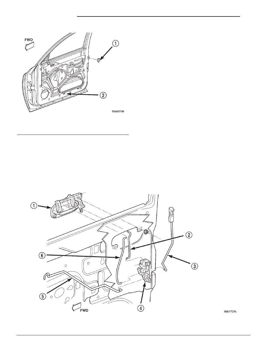
Fig. 4 Outside Door Handle

1 - OUTSIDE HANDLE
2 - LOCK CYLINDER TO LATCH ROD
3 - LOCK BUTTON TO LATCH ROD

4 - LATCH
5 - INSIDE HANDLE TO LATCH ROD
6 - OUTSIDE HANDLE TO LATCH ROD

Fig. 3 Access Plug

1 - ACCESS PLUG
2 - DOOR

23 - 64

DOOR - FRONT

AN

FRONT DOOR OUTSIDE HANDLE (Continued)

FRONT DOOR HINGE

DESCRIPTION

The hinge pin is not serviceable. Replace the hinge

if the hinge pin is damaged.

REMOVAL

(1) Release door latch and open door.
(2) Support door on a suitable lifting device.
(3) Using a suitable marker, mark the outline of

the door hinge on the hinge pillar and door end
frame to aid installation.

(4) Remove bolts attaching hinge to door (Fig. 6).
(5) Remove bolts attaching door hinge to hinge pil-

lar.

(6) Separate door hinge from vehicle.

INSTALLATION

(1)

If necessary, paint replacement door hinge

before installation.

(2) Position door hinge on hinge pillar using align-

ment marks.

(3) Install bolts attaching door hinge to hinge pil-

lar. Tighten bolts to 28 N·m (21 ft. lbs.) torque.

(4) Install bolts attaching hinge to door. Tighten

bolts to 28 N·m (21 ft. lbs.) torque.

FRONT DOOR INSIDE HANDLE
ACTUATOR

DESCRIPTION

The front door inside handle actuator is heat

staked to the trim panel. If the handle needs servic-
ing, refer to the heat staking procedure located in
this section.

FRONT DOOR LATCH

REMOVAL

(1) Remove door trim panel.
(2) Peel back water dam as necessary.
(3) For access to latch, roll up glass and remove

bolts attaching rearward glass run channel to door.
Move and secure glass run channel.

Fig. 5 Lower Glass Run

1 - UPPER GLASS RUN CHANNEL
2 - UPPER CHANNEL
3 - LOWER GLASS RUN CHANNEL
4 - LOWER CHANNEL
5 - REGULATOR
6 - DOOR GLASS

Fig. 6 Door Hinge

1 - BOLT
2 - HINGE
3 - HINGE PILLAR

AN

DOOR - FRONT

23 - 65

FDR LOWER GLASS RUN CHANNELS (Continued)

(4) Remove screws attaching latch to door shut

face (Fig. 7).

(5) Disengage wire harness connector for power

door locks, if equipped.

(6) Disengage lock button to latch rod from the

latch.

(7) Disengage lock cylinder to latch rod from the

latch (Fig. 4).

(8) Disengage inside handle to latch rod from the

latch.

(9) Disengage outside handle to latch rod from the

latch.

(10) Separate latch from door.

INSTALLATION

(1) Engage latch rod to outside handle.
(2) Engage inside handle to latch rod to the latch.
(3) Engage lock cylinder to latch rod to the latch.
(4) Engage lock button to latch rod to the latch.
(5) Position latch in door.
(6) Install screws attaching latch to door shut face.

Tighten the screws to 9.6 N·m (85 in. lbs.) torque.

(7) Engage outside handle to latch rod to the latch.
(8) Engage wire harness connector for power door

locks, if equipped.

(9) Install rearward glass run channel.
(10) Install water dam.
(11) Install door trim panel.
(12) Using the access hole in the door shut face,

loosen the latch adjustment screw and ensure the
outside door handle is flush with door outer panel.
Tighten the adjustment screw.

ADJUSTMENTS

(1) Insert a torx driver through the round hole in

the door end frame near the latch striker opening
(Fig. 8).

(2) Loosen torx head screw on the side of the latch

linkage.

(3) Lift upward on outside door handle and release

it.

(4) Tighten torx head screw on latch.
(5) Verify latch operation.

FRONT DOOR LATCH STRIKER

REMOVAL

(1) Use a wax crayon or equivalent and mark the

position of the striker on the B-pillar.

(2) Remove the screws attaching the striker and

spacer to the B-pillar (Fig. 9).

(3) Separate the striker from the B-pillar.

INSTALLATION

(1) Using the alignment marks, position the spacer

and striker on the B-Pillar.

(2) Install the screws. Tighten the screw to 28.2

N·m (250 in. lbs.) torque.

Fig. 7 Latch

1 - LATCH
2 - DOOR

Fig. 8 Door Latch Adjustment

1 - OUTSIDE DOOR HANDLE
2 - DOOR LATCH ADJUSTMENT ACCESS

23 - 66

DOOR - FRONT

AN

FRONT DOOR LATCH (Continued)

FRONT DOOR LOCK
CYLINDER

LOCK CYLINDERS

Ignition, door, deck lid, and rear hatch lock cylin-

ders are all codable to the key. Lock barrels, tum-
blers, and tumbler springs are available to allow the
technician to change replacement locks cylinders to
match the customer’s original key set. See the appro-
priate section in this manual for lock cylinder
removal. See the Mopar

t catalogue for part numbers

and lock coding procedures.

REMOVAL

(1) Remove door trim panel.
(2) Remove outside handle.
(3) Disengage lock cylinder to latch rod from the

lock cylinder.

(4) Using a small flat blade, pry lock cylinder

retaining clip from lock cylinder housing/outside han-
dle (Fig. 10).

(5) Push lock cylinder out of lock cylinder housing/

outside handle.

INSTALLATION

(1) Push lock cylinder into lock cylinder housing/

outside handle. Ensure the lock cylinder is fully
seated in the handle.

(2) Install lock cylinder retaining clip. Ensure the

clip is fully seated.

(3) Engage lock cylinder to latch rod to the lock

cylinder.

(4) Install outside handle.
(5) Install door trim panel.

TRIM PANEL

REMOVAL

(1) Release door latch and open door.
(2) Roll window down.
(3) Remove window crank (Fig. 11), if equipped.
(4) Remove screws attaching trim panel to door

(Fig. 12) and (Fig. 13).

CAUTION: Do not forcibly pull trim panel from door,
damage to trim panel may occur.

Fig. 9 Front Door Latch Striker

1 - TAPPING PLATE
2 - SPACER
3 - STRIKER

Fig. 10 Lock Cylinder

1 - LOCK CYLINDER TO LATCH ROD
2 - STUD
3 - OUTSIDE HANDLE
4 - RETAINING CLIP
5 - STUD
6 - LOCK CYLINDER
7 - LOCK BUTTON ROD

AN

DOOR - FRONT

23 - 67

FRONT DOOR LATCH STRIKER (Continued)


Content   ..  767  768  769  770   ..