Dodge Dakota (R1). Manual - part 722


  Index      Dodge     Dodge Dakota (R1) - service repair manual 2000 year


Search            


Content   ..  720  721  722  723   ..


Dodge Dakota (R1). Manual - part 722


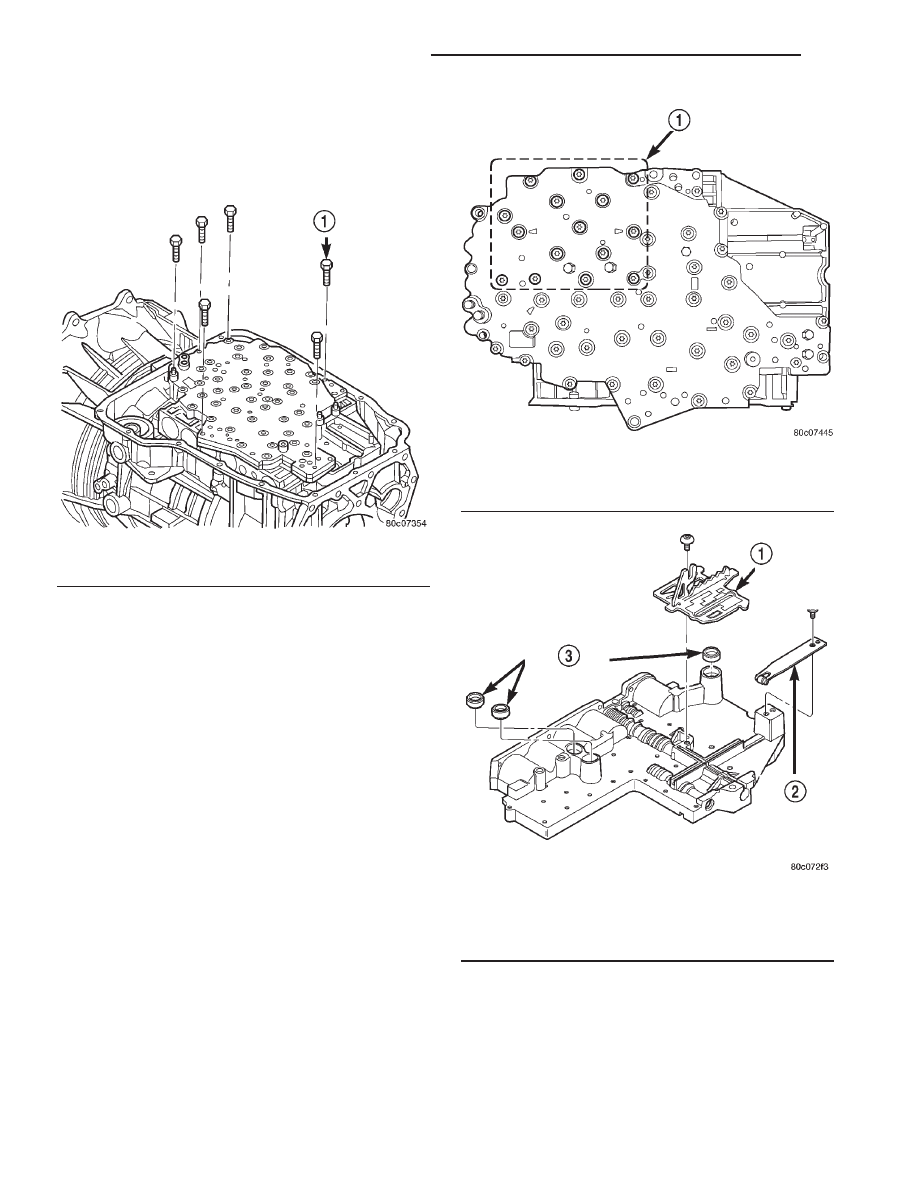
(7) Remove bolts attaching valve body to transmis-

sion case (Fig. 122).

(8) Lower the valve body and work the electrical

connector out of transmission case.

(9) Separate the valve body from the transmission.

DISASSEMBLY

(1) Remove the screws holding the solenoid and

pressure switch assembly to the valve body (Fig.
123). Do not remove the screws on the top of the sole-
noid and pressure switch assembly.

(2) Separate the solenoid and pressure switch

assembly from the valve body.

(3) Remove the screw holding the detent spring

(Fig. 124) onto the valve body.

(4) Remove the detent spring from the valve body.
(5) Remove the TRS selector plate from the valve

body and the manual valve.

(6) Remove the clutch passage seals from the valve

body, if necessary.

Fig. 122 Valve Body Bolts

1 - VALVE BODY TO CASE BOLT (6)

Fig. 123 Solenoid and Pressure Switch Assembly

Screws

1 - SOLENOID PACK BOLTS (15)

Fig. 124 Valve Body External Components

1 - TRS SELECTOR PLATE
2 - DETENT SPRING
3 - CLUTCH PASSAGE SEALS

21 - 532

AUTOMATIC TRANSMISSION - 45RFE

AN

VALVE BODY (Continued)

(7) Remove the screws holding the accumulator

cover onto the valve body (Fig. 125).

(8) Remove the accumulator springs and pistons

from the valve body. Note which accumulator piston
and spring belong in each location.

(9) Place the valve body on the bench with the

transfer plate upward.

NOTE: The valve body contains seven check balls.
The transfer plate must be placed upward to pre-
vent losing the check balls when the transfer plate
is removed from the valve body.

(10) Remove the screws holding the valve body to

the valve body transfer plate.

(11) Remove the transfer plate from the valve

body. Note the location of all check balls (Fig. 126).

(12) Remove the check balls from the valve body.

Fig. 125 Valve Body Components

1 - LOW/REVERSE ACCUMULATOR

6 - OVERDRIVE ACCUMULATOR

2 - LOW/REVERSE SWITCH VALVE

7 - UNDERDRIVE ACCUMULATOR

3 - UPPER VALVE BODY

8 - 4C ACCUMULATOR

4 - MANUAL VALVE

9 - 2C ACCUMULATOR

5 - SOLENOID SWITCH VALVE

Fig. 126 Check Ball Locations

AN

AUTOMATIC TRANSMISSION - 45RFE

21 - 533

VALVE BODY (Continued)

(13) Remove the retainers securing the solenoid

switch valve, manual valve, and the low/reverse
switch valve into the valve body and remove the
associated valve and spring. Tag each valve and
spring combination with location information to aid
in assembly. (Fig. 127)

CLEANING

Clean the valve housings, valves, plugs, springs,

and separator plates with a standard parts cleaning
solution only. Do not use gasoline, kerosene, or any
type of caustic solution. (Fig. 128)

Do not immerse any of the electrical components in

cleaning solution. Clean the electrical components by
wiping them off with dry shop towels only.

Dry all except the electrical parts with compressed

air. Make sure all passages are clean and free from
obstructions. Do not use rags or shop towels to
dry or wipe off valve body components. Lint

from these materials can stick to valve body
parts, interfere with valve operation, and clog
filters and fluid passages.

INSPECTION

Inspect all of the valve body mating surfaces for

scratches, nicks, burrs, or distortion. Use a straight-
edge to check surface flatness. Minor scratches may
be removed with crocus cloth using only very light
pressure.

Minor distortion of a valve body mating surface

may be corrected by smoothing the surface with a
sheet of crocus cloth. Position the crocus cloth on a
surface plate, sheet of plate glass or equally flat sur-
face. If distortion is severe or any surfaces are
heavily scored, the valve body will have to be
replaced.

Fig. 127 Valve Body Components

1 - SOLENOID SWITCH VALVE
2 - MANUAL VALVE
3 - LOW REVERSE SWITCH VALVE
4 - LOW REVERSE ACCUMULATOR
5 - 2ND CLUTCH ACCUMULATOR
6 - UNDERDRIVE ACCUMULATOR
7 - OVERDRIVE ACCUMULATOR
8 - 4TH CLUTCH ACCUMULATOR
9 - CHECK BALLS (7)

Fig. 128 Valve Body Components

1 - SOLENOID SWITCH VALVE
2 - MANUAL VALVE
3 - LOW REVERSE SWITCH VALVE
4 - LOW REVERSE ACCUMULATOR
5 - 2ND CLUTCH ACCUMULATOR
6 - UNDERDRIVE ACCUMULATOR
7 - OVERDRIVE ACCUMULATOR
8 - 4TH CLUTCH ACCUMULATOR
9 - CHECK BALLS (7)

21 - 534

AUTOMATIC TRANSMISSION - 45RFE

AN

VALVE BODY (Continued)

Inspect

the

valves

and

plugs

(Fig.

129)

for

scratches, burrs, nicks, or scores. Minor surface
scratches on steel valves and plugs can be removed
with crocus cloth but do not round off the edges
of the valve or plug lands. 
Maintaining sharpness
of these edges is vitally important. The edges prevent
foreign matter from lodging between the valves and
plugs and the bore.

Inspect all the valve and plug bores in the valve

body. Use a penlight to view the bore interiors.
Replace the valve body if any bores are distorted or
scored. Inspect all of the valve body springs. The
springs must be free of distortion, warpage or broken
coils.

Trial fit each valve and plug in its bore to check

freedom of operation. When clean and dry, the valves
and plugs should drop freely into the bores.

Valve body bores do not change dimensionally with

use. If the valve body functioned correctly when new,

it will continue to operate properly after cleaning and
inspection. It should not be necessary to replace a
valve body assembly unless it is damaged in han-
dling.

Inspect all the accumulator bores in the valve body.

Use a penlight to view the bore interiors. Replace the
valve body if any bores are distorted or scored.
Inspect all of the accumulator springs. The springs
must be free of distortion, warpage or broken coils.

Inspect all the fluid seals on the valve body (Fig.

130). Replace any seals that are cracked, distorted, or
damaged in any way. These seals pass fluid pressure
directly to the clutches. Any pressure leak at these
points, may cause transmission performance prob-
lems.

ASSEMBLY

(1) Lubricate valves, springs, and the housing

valve bores with clean transmission fluid.

(2) Install solenoid switch valve, manual valve,

and the low/reverse switch valve into the valve body.

(3) Install the retainers to hold each valve into the

valve body.

(4) Install the valve body check balls into their

proper locations.

(5) Position the transfer plate onto the valve body.

Fig. 129 Valve Body Components

1 - SOLENOID SWITCH VALVE
2 - MANUAL VALVE
3 - LOW REVERSE SWITCH VALVE
4 - LOW REVERSE ACCUMULATOR
5 - 2ND CLUTCH ACCUMULATOR
6 - UNDERDRIVE ACCUMULATOR
7 - OVERDRIVE ACCUMULATOR
8 - 4TH CLUTCH ACCUMULATOR
9 - CHECK BALLS (7)

Fig. 130 Valve Body Seals

1 - UNDERDRIVE ACCUMULATOR (2 SPRINGS)
2 - 4TH CLUTCH ACCUMULATOR (2 SPRINGS)
3 - 2ND CLUTCH ACCUMULATOR (2 SPRINGS)
4 - LOW REVERSE ACCUMULATOR (2 SPRINGS)
5 - LOW/REVERSE PASSAGE SEAL
6 - 2ND CLUTCH PASSAGE SEAL
7 - 4TH CLUTCH PASSAGE SEAL
8 - OVERDRIVE ACCUMULATOR (1 SPRING)

AN

AUTOMATIC TRANSMISSION - 45RFE

21 - 535

VALVE BODY (Continued)


Content   ..  720  721  722  723   ..