Dodge Dakota (R1). Manual - part 684


  Index      Dodge     Dodge Dakota (R1) - service repair manual 2000 year


Search            


Content   ..  682  683  684  685   ..


Dodge Dakota (R1). Manual - part 684


The selective snap ring thicknesses are:
• 0.107 - 0.109 in.

• 0.098 - 0.100 in.

• 0.095 - 0.097 in.

• 0.083 - 0.085 in.

• 0.076 - 0.078 in.

• 0.071 - 0.073 in.

• 0.060 - 0.062 in.
(16) Coat rear clutch thrust washer with petro-

leum jelly and install washer over input shaft and
into clutch retainer (Fig. 233). Use enough petroleum
jelly to hold washer in place.

(17) Set rear clutch aside for installation during

final assembly.

REAR SERVO

DESCRIPTION

The rear (low/reverse) servo consists of a single

stage or diameter piston and a spring loaded plug.
The spring is used to cushion the application of the
rear (low/reverse) band.

OPERATION

While in the de-energized state (no pressure

applied), the piston is held up in its bore by the pis-
ton spring. The plug is held down in its bore, in the
piston, by the plug spring. When pressure is applied
to the top of the piston, the plug is forced down in its
bore, taking up any clearance. As the piston moves, it
causes the plug spring to compress, and the piston
moves down over the plug. The piston continues to
move down until it hits the shoulder of the plug and
fully applies the band. The period of time from the
initial application, until the piston is against the
shoulder of the plug, represents a reduced shocking
of the band that cushions the shift.

DISASSEMBLY

(1) Remove small snap-ring and remove plug and

spring from servo piston (Fig. 234).

(2) Remove and discard servo piston seal ring.

CLEANING

Remove and discard the servo piston seal ring (Fig.

235). Then clean the servo components with solvent
and dry with compressed air. Replace either spring if
collapsed, distorted or broken. Replace the plug and
piston if cracked, bent, or worn. Discard the servo
snap-rings and use new ones at assembly.

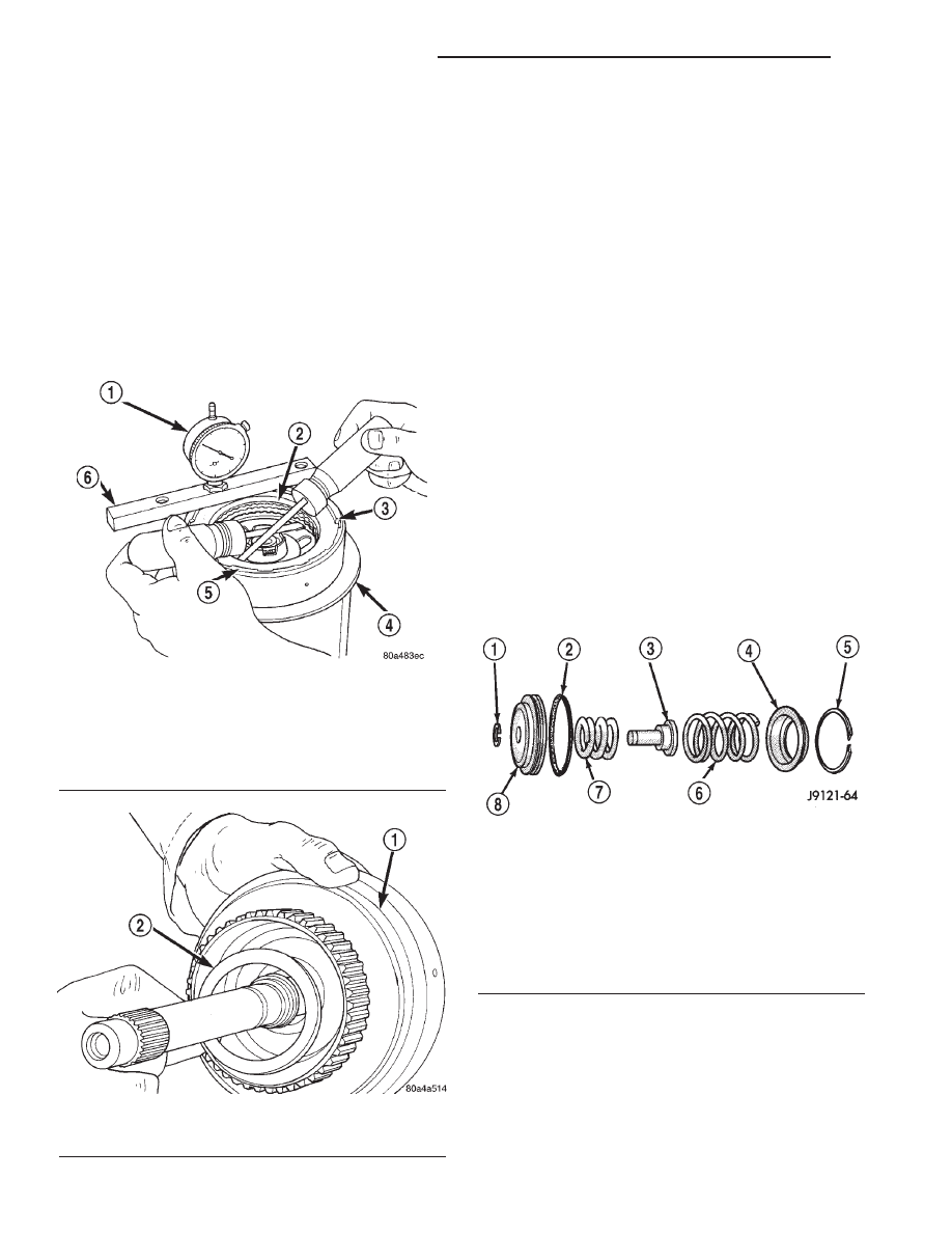
Fig. 232 Checking Rear Clutch Pack Clearance

1 - DIAL INDICATOR
2 - PRESSURE PLATE
3 - SNAP-RING
4 - STAND
5 - REAR CLUTCH
6 - GAUGE BAR

Fig. 233 Installing Rear Clutch Thrust Washer

1 - REAR CLUTCH RETAINER
2 - REAR CLUTCH THRUST WASHER

Fig. 234 Rear Servo Components

1 - SNAP-RING
2 - PISTON SEAL
3 - PISTON PLUG
4 - SPRING RETAINER
5 - SNAP-RING
6 - PISTON SPRING
7 - CUSHION SPRING
8 - PISTON

21 - 380

AUTOMATIC TRANSMISSION - 46RE

AN

REAR CLUTCH (Continued)

ASSEMBLY

(1) Lubricate piston and guide seals (Fig. 236)

with petroleum jelly. Lubricate other servo parts with
Mopar

t ATF +4, type 9602, transmission fluid.

(2) Install new seal ring on servo piston.
(3) Assemble piston, plug, spring and new snap-

ring.

(4) Lubricate piston seal lip with petroleum jelly.

SHIFT MECHANISM

DESCRIPTION

The gear shift mechanism provides six shift posi-

tions which are:

• PARK (P)

• REVERSE (R)

• NEUTRAL (N)

• DRIVE (D)

• Manual SECOND (2)

• Manual LOW (1)

OPERATION

Manual LOW (1) range provides first gear only.

Overrun braking is also provided in this range. Man-
ual SECOND (2) range provides first and second gear
only.

DRIVE range provides first, second third and over-

drive fourth gear ranges. The shift into overdrive
fourth gear range occurs only after the transmission
has completed the shift into D third gear range. No
further movement of the shift mechanism is required
to complete the 3-4 shift.

The fourth gear upshift occurs automatically when

the overdrive selector switch is in the ON position.
No upshift to fourth gear will occur if any of the fol-
lowing are true:

• The transmission fluid temperature is below 10°

C (50° F) or above 121° C (250° F).

• The shift to third is not yet complete.

• Vehicle speed is too low for the 3-4 shift to occur.

• Battery temperature is below -5° C (23° F).

SOLENOID

DESCRIPTION

The typical electrical solenoid used in automotive

applications is a linear actuator. It is a device that
produces motion in a straight line. This straight line
motion can be either forward or backward in direc-
tion, and short or long distance.

A solenoid is an electromechanical device that uses

a magnetic force to perform work. It consists of a coil
of wire, wrapped around a magnetic core made from
steel or iron, and a spring loaded, movable plunger,
which performs the work, or straight line motion.

Fig. 235 Rear Servo Components

1 - SNAP-RING
2 - PISTON SEAL
3 - PISTON PLUG
4 - SPRING RETAINER
5 - SNAP-RING
6 - PISTON SPRING
7 - CUSHION SPRING
8 - PISTON

Fig. 236 Rear Servo Components

1 - SNAP-RING
2 - PISTON SEAL
3 - PISTON PLUG
4 - SPRING RETAINER
5 - SNAP-RING
6 - PISTON SPRING
7 - CUSHION SPRING
8 - PISTON

AN

AUTOMATIC TRANSMISSION - 46RE

21 - 381

REAR SERVO (Continued)

The solenoids used in transmission applications

are attached to valves which can be classified as nor-
mally open 
or normally closed. The normally
open 
solenoid valve is defined as a valve which
allows hydraulic flow when no current or voltage is
applied to the solenoid. The normally closed sole-
noid valve is defined as a valve which does not allow
hydraulic flow when no current or voltage is applied
to the solenoid. These valves perform hydraulic con-
trol functions for the transmission and must there-
fore be durable and tolerant of dirt particles. For
these reasons, the valves have hardened steel pop-
pets and ball valves. The solenoids operate the valves
directly, which means that the solenoids must have
very high outputs to close the valves against the siz-
able flow areas and line pressures found in current
transmissions. Fast response time is also necessary
to ensure accurate control of the transmission.

The strength of the magnetic field is the primary

force that determines the speed of operation in a par-
ticular solenoid design. A stronger magnetic field will
cause the plunger to move at a greater speed than a
weaker one. There are basically two ways to increase
the force of the magnetic field:

• Increase the amount of current applied to the

coil or

• Increase the number of turns of wire in the coil.
The most common practice is to increase the num-

ber of turns by using thin wire that can completely
fill the available space within the solenoid housing.
The strength of the spring and the length of the
plunger also contribute to the response speed possi-
ble by a particular solenoid design.

A solenoid can also be described by the method by

which it is controlled. Some of the possibilities
include variable force, pulse-width modulated, con-
stant ON, or duty cycle. The variable force and pulse-
width modulated versions utilize similar methods to
control the current flow through the solenoid to posi-
tion the solenoid plunger at a desired position some-
where between full ON and full OFF. The constant
ON and duty cycled versions control the voltage
across the solenoid to allow either full flow or no flow
through the solenoid’s valve.

OPERATION

When an electrical current is applied to the sole-

noid coil, a magnetic field is created which produces
an attraction to the plunger, causing the plunger to
move and work against the spring pressure and the
load applied by the fluid the valve is controlling. The
plunger is normally directly attached to the valve
which it is to operate. When the current is removed
from the coil, the attraction is removed and the
plunger will return to its original position due to
spring pressure.

The plunger is made of a conductive material and

accomplishes this movement by providing a path for
the magnetic field to flow. By keeping the air gap
between the plunger and the coil to the minimum
necessary to allow free movement of the plunger, the
magnetic field is maximized.

SPEED SENSOR

DESCRIPTION

The speed sensor (Fig. 237) is located in the over-

drive gear case. The sensor is positioned over the
park gear and monitors transmission output shaft
rotating speed.

OPERATION

Speed sensor signals are triggered by the park

gear lugs as they rotate past the sensor pickup face.
Input signals from the sensor are sent to the trans-
mission control module for processing. Signals from
this sensor are shared with the powertrain control
module.

Fig. 237 Transmission Output Speed Sensor

1 - TRANSMISSION OUTPUT SHAFT SPEED SENSOR
2 - SEAL

21 - 382

AUTOMATIC TRANSMISSION - 46RE

AN

SOLENOID (Continued)

THROTTLE VALVE CABLE

DESCRIPTION

Transmission throttle valve cable (Fig. 238) adjust-

ment is extremely important to proper operation.
This adjustment positions the throttle valve, which
controls shift speed, quality, and part-throttle down-
shift sensitivity.

If cable setting is too loose, early shifts and slip-

page between shifts may occur. If the setting is too
tight, shifts may be delayed and part throttle down-
shifts may be very sensitive.

The transmission throttle valve is operated by a

cam on the throttle lever. The throttle lever is oper-
ated by an adjustable cable (Fig. 239). The cable is
attached to an arm mounted on the throttle lever
shaft. A retaining clip at the engine-end of the cable
is removed to provide for cable adjustment. The
retaining clip is then installed back onto the throttle
valve cable to lock in the adjustment.

ADJUSTMENTS - TRANSMISSION THROTTLE
VALVE CABLE

A correctly adjusted throttle valve cable will cause

the throttle lever on the transmission to move simul-
taneously with the throttle body lever from the idle
position. Proper adjustment will allow simultaneous
movement without causing the transmission throttle
lever to either move ahead of, or lag behind the lever
on the throttle body.

ADJUSTMENT VERIFICATION

(1) Turn ignition key to OFF position.
(2) Remove air cleaner.
(3) Verify that lever on throttle body is at curb idle

position (Fig. 240). Then verify that the transmission
throttle lever (Fig. 241) is also at idle (fully forward)
position.

(4) Slide cable off attachment stud on throttle body

lever.

Fig. 238 Throttle Valve Cable Attachment - At

Engine

1 - THROTTLE VALVE CABLE
2 - CABLE BRACKET
3 - THROTTLE BODY LEVER
4 - ACCELERATOR CABLE
5 - SPEED CONTROL CABLE

Fig. 239 Throttle Valve Cable at Throttle Linkage

1 - THROTTLE LINKAGE
2 - THROTTLE VALVE CABLE LOCKING CLIP
3 - THROTTLE VALVE CABLE

AN

AUTOMATIC TRANSMISSION - 46RE

21 - 383


Content   ..  682  683  684  685   ..