Dodge Dakota (R1). Manual - part 683


  Index      Dodge     Dodge Dakota (R1) - service repair manual 2000 year


Search            


Content   ..  681  682  683  684   ..


Dodge Dakota (R1). Manual - part 683


REAR CLUTCH

DESCRIPTION

The rear clutch assembly (Fig. 229) is composed of

the rear clutch retainer, pressure plate, clutch plates,
driving discs, piston, Belleville spring, and snap-
rings. The Belleville spring acts as a lever to multi-
ply the force applied on to it by the apply piston. The
increased apply force on the rear clutch pack, in com-
parison to the front clutch pack, is needed to hold
against the greater torque load imposed onto the rear
pack. The rear clutch is directly behind the front
clutch and is considered a driving component.

NOTE: The number of discs and plates may vary
with each engine and vehicle combination.

OPERATION

To apply the clutch, pressure is applied between

the clutch retainer and piston. The fluid pressure is
provided by the oil pump, transferred through the
control valves and passageways, and enters the
clutch through the hub of the reaction shaft support.
With pressure applied between the clutch retainer
and piston, the piston moves away from the clutch
retainer and compresses the clutch pack. This action
applies the clutch pack, allowing torque to flow
through the input shaft into the driving discs, and
into the clutch plates and pressure plate that are
lugged to the clutch retainer. The waved spring is
used to cushion the application of the clutch pack.
The snap-ring is selective and used to adjust clutch
pack clearance.

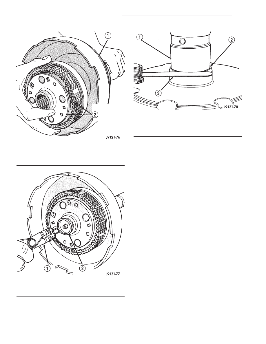
Fig. 226 Installing Front Planetary And Annulus

Gear Assembly

1 - DRIVING SHELL
2 - ASSEMBLED FRONT PLANETARY AND ANNULUS GEARS

Fig. 227 Installing Planetary Snap-Ring

1 - SNAP-RING PLIERS
2 - PLANETARY SNAP-RING

Fig. 228 Checking Planetary Geartrain End Play

1 - OUTPUT SHAFT
2 - REAR ANNULUS GEAR
3 - FEELER GAUGE

21 - 376

AUTOMATIC TRANSMISSION - 46RE

AN

REAR CLUTCH (Continued)

When pressure is released from the piston, the

spring returns the piston to its fully released position
and disengages the clutch. The release spring also
helps to cushion the application of the clutch assem-
bly. When the clutch is in the process of being
released by the release spring, fluid flows through a
vent and one-way ball-check-valve located in the pis-
ton. The check-valve is needed to eliminate the pos-
sibility of plate drag caused by centrifugal force
acting on the residual fluid trapped in the clutch pis-
ton retainer.

DISASSEMBLY

(1) Remove fiber thrust washer from forward side

of clutch retainer.

(2) Remove input shaft front and rear seal rings.
(3) Remove selective clutch pack snap-ring (Fig.

230).

(4) Remove the reaction plate, clutch discs, steel

plates, pressure plate, wave spring, spacer ring, and
piston spring (Fig. 230).

(5) Remove clutch piston with rotating motion.
(6) Remove and discard piston seals.
(7) Remove input shaft retaining ring. It may be

necessary to press the input shaft in slightly to
relieve tension on the retaining ring

(8) Press input shaft out of retainer with shop

press and suitable size press tool. Use a suitably
sized press tool to support the retainer as close to the
input shaft as possible.

CLEANING

Clean the clutch components with solvent and dry

them with compressed air. Do not use rags or shop
towels to dry any of the clutch parts. Lint from such
materials will adhere to component surfaces and
could restrict or block fluid passages after assembly.

Fig. 229 Rear Clutch Components

1 - REAR CLUTCH RETAINER

11 - REACTION PLATE

2 - TORLON™ SEAL RINGS

12 - CLUTCH PLATES

3 - INPUT SHAFT

13 - WAVE SPRING

4 - PISTON RETAINER

14 - SPACER RING

5 - OUTPUT SHAFT THRUST WASHER

15 - PISTON

6 - INNER PISTON SEAL

16 - OUTER PISTON SEAL

7 - PISTON SPRING

17 - REAR SEAL RING

8 - PRESSURE PLATE

18 - FIBER THRUST WASHER

9 - CLUTCH DISCS

19 - RETAINING RING

10 - SNAP-RING (SELECTIVE)

AN

AUTOMATIC TRANSMISSION - 46RE

21 - 377

REAR CLUTCH (Continued)

INSPECTION

Replace the clutch discs if warped, worn, scored,

burned/charred, the lugs are damaged, or if the fac-
ing is flaking off. Replace the top and bottom pres-
sure plates if scored, warped, or cracked. Be sure the
driving lugs on the pressure and clutch plates are
also in good condition. The lugs must not be bent,
cracked or damaged in any way.

Replace the piston spring and wave spring if either

part is distorted, warped or broken.

Check the lug grooves in the clutch retainer. The

clutch and pressure plates should slide freely in the
slots. Replace the retainer if the grooves are worn or
damaged. Also check action of the check balls in the
retainer and piston. Each check ball must move
freely and not stick.

Replace the retainer bushing if worn, scored, or

doubt exists about bushing condition.

Inspect the piston and retainer seal surfaces for

nicks or scratches. Minor scratches can be removed
with crocus cloth. However, replace the piston and/or
retainer if the seal surfaces are seriously scored.

Check condition of the fiber thrust washer and

metal output shaft thrust washer. Replace either
washer if worn or damaged.

Check condition of the seal rings on the input shaft

and clutch retainer hub. Replace the seal rings only
if worn, distorted, or damaged. The input shaft front
seal ring is teflon with chamfered ends. The rear ring
is metal with interlocking ends.

Check the input shaft for wear, or damage. Replace

the shaft if worn, scored or damaged in any way.

Fig. 230 Rear Clutch Components

1 - REAR CLUTCH RETAINER

11 - REACTION PLATE

2 - TORLON™ SEAL RINGS

12 - CLUTCH PLATES

3 - INPUT SHAFT

13 - WAVE SPRING

4 - PISTON RETAINER

14 - SPACER RING

5 - OUTPUT SHAFT THRUST WASHER

15 - PISTON

6 - INNER PISTON SEAL

16 - OUTER PISTON SEAL

7 - PISTON SPRING

17 - REAR SEAL RING

8 - PRESSURE PLATE

18 - FIBER THRUST WASHER

9 - CLUTCH DISCS

19 - RETAINING RING

10 - SNAP-RING (SELECTIVE)

21 - 378

AUTOMATIC TRANSMISSION - 46RE

AN

REAR CLUTCH (Continued)

ASSEMBLY

(1) Soak clutch discs in transmission fluid while

assembling other clutch parts.

(2) Install new seal rings on clutch retainer hub

and input shaft if necessary.

(a) Be sure clutch hub seal ring is fully seated in

groove and is not twisted.
(3) Lubricate splined end of input shaft and clutch

retainer with transmission fluid. Then partially press
input shaft into retainer (Fig. 231). Use a suitably
sized press tool to support retainer as close to input
shaft as possible.

(4) Install input shaft retaining ring.
(5) Press the input shaft the remainder of the way

into the clutch retainer.

(6) Install new seals on clutch piston. Be sure lip

of each seal faces interior of clutch retainer.

(7) Lubricate lip of piston seals with generous

quantity of Mopar

t Door Ease. Then lubricate

retainer hub and bore with light coat of transmission
fluid.

(8) Install clutch piston in retainer. Use twisting

motion to seat piston in bottom of retainer. A thin
strip of plastic (about 0.020

9 thick), can be used to

guide seals into place if necessary.

CAUTION: Never push the clutch piston straight in.
This will fold the seals over causing leakage and
clutch slip. In addition, never use any type of metal
tool to help ease the piston seals into place. Metal
tools will cut, shave, or score the seals.

(9) Install piston spring in retainer and on top of

piston. Concave side of spring faces downward
(toward piston).

(10) Install the spacer ring and wave spring into

the retainer. Be sure spring is completely seated in
retainer groove.

(11) Install pressure plate (Fig. 230). Ridged side

of plate faces downward (toward piston) and flat side
toward clutch pack.

(12) Install first clutch disc in retainer on top of

pressure plate. Then install a clutch plate followed
by a clutch disc until entire clutch pack is installed
(4 discs and 3 plates are required) (Fig. 230).

(13) Install the reaction plate.
(14) Install selective snap-ring. Be sure snap-ring

is fully seated in retainer groove.

(15) Using a suitable gauge bar and dial indicator,

measure clutch pack clearance (Fig. 232).

(a) Position gauge bar across the clutch drum

with the dial indicator pointer on the pressure
plate (Fig. 232).

(b) Using two small screw drivers, lift the pres-

sure plate and release it.

(c) Zero the dial indicator.
(d) Lift the pressure plate until it contacts the

snap-ring and record the dial indicator reading.
Clearance should be 0.635 - 0.914 mm (0.025 -

0.036 in.). If clearance is incorrect, steel plates, discs,
selective snap ring and pressure plates may have to
be changed.

Fig. 231 Pressing Input Shaft Into Rear Clutch

Retainer

1 - INPUT SHAFT
2 - REAR CLUTCH RETAINER
3 - PRESS RAM

AN

AUTOMATIC TRANSMISSION - 46RE

21 - 379

REAR CLUTCH (Continued)


Content   ..  681  682  683  684   ..