Dodge Dakota (R1). Manual - part 672


  Index      Dodge     Dodge Dakota (R1) - service repair manual 2000 year


Search            


Content   ..  670  671  672  673   ..


Dodge Dakota (R1). Manual - part 672


(12) Compress spring retainer and piston springs

with Tool C-3863-A.

(13) Install spring retainer snap-ring and remove

compressor tool.

(14) Install clutch plates and discs (Fig. 94). Three

clutch discs, three steel plates and one reaction plate
are required.

(15) Install reaction plate followed by waved snap-

ring.

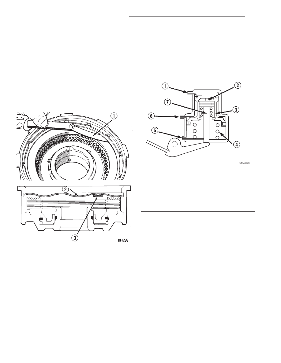
(16) Check clutch pack clearance with feeler gauge

(Fig. 98). Clearance between waved spring and pres-
sure plate should 1.78 - 3.28 mm (0.070 - 0.129 in.).
If clearance is incorrect, clutch plates, clutch discs,
snap-ring, or pressure plate may have to be changed.

FRONT SERVO

DESCRIPTION

The kickdown servo (Fig. 99) consists of a two-land

piston with an inner piston, a piston rod and guide,
and a return spring. The dual-land piston uses seal
rings on its outer diameters and an O-ring for the
inner piston.

OPERATION

The application of the piston is accomplished by

applying pressure between the two lands of the pis-
ton. The pressure acts against the larger lower land
to push the piston downward, allowing the piston rod
to extend though its guide against the apply lever.
Release of the servo at the 2-3 upshift is accom-
plished by a combination of spring and line pressure,
acting on the bottom of the larger land of the piston.
The small piston is used to cushion the application of
the band by bleeding oil through a small orifice in
the larger piston. The release timing of the kickdown
servo is very important to obtain a smooth but firm
shift. The release has to be very quick, just as the
front clutch application is taking place. Otherwise,
engine runaway or a shift hesitation will occur. To
accomplish this, the band retains its holding capacity
until the front clutch is applied, giving a small
amount of overlap between them.

Fig. 98 Typical Method Of Measuring Front Clutch

Pack Clearance

1 - FEELER GAUGE
2 - WAVED SNAP-RING
3 - FEELER GAUGE

Fig. 99 Front Servo

1 - VENT
2 - INNER PISTON
3 - PISTON
4 - SPRING
5 - RELEASE PRESSURE
6 - APPLY PRESSURE
7 - PISTON ROD

21 - 332

AUTOMATIC TRANSMISSION - 46RE

AN

FRONT CLUTCH (Continued)

DISASSEMBLY

(1) Remove seal ring from rod guide (Fig. 100).
(2) Remove small snap-ring from servo piston rod.

Then remove piston rod, spring and washer from pis-
ton.

(3) Remove and discard servo component O-ring

and seal rings.

CLEANING

Clean the servo piston components (Fig. 101) with

solvent and dry them with compressed air.

INSPECTION

Inspect the servo components (Fig. 102). Replace

the springs if collapsed, distorted or broken. Replace
the guide, rod and piston if cracked, bent, or worn.
Discard the servo snap-ring if distorted or warped.

Check the servo piston bore for wear. If the bore is

severely scored, or damaged, it will be necessary to
replace the case.

Replace any servo component if doubt exists about

condition. Do not reuse suspect parts.

Fig. 100 Front Servo

1 - PISTON RINGS
2 - SERVO PISTON
3 - O-RING
4 - SNAP-RING
5 - PISTON ROD GUIDE
6 - SEAL RING
7 - SNAP-RING
8 - SERVO SPRING
9 - WASHER
10 - SPRING
11 - PISTON ROD

Fig. 101 Front Servo

1 - VENT
2 - INNER PISTON
3 - PISTON
4 - SPRING
5 - RELEASE PRESSURE
6 - APPLY PRESSURE
7 - PISTON ROD

Fig. 102 Front Servo

1 - PISTON RINGS
2 - SERVO PISTON
3 - O-RING
4 - SNAP-RING
5 - PISTON ROD GUIDE
6 - SEAL RING
7 - SNAP-RING
8 - SERVO SPRING
9 - WASHER
10 - SPRING
11 - PISTON ROD

AN

AUTOMATIC TRANSMISSION - 46RE

21 - 333

FRONT SERVO (Continued)

ASSEMBLY

Clean and inspect front servo components.
(1) Lubricate new o-ring and seal rings with petro-

leum jelly and install them on piston, guide and rod.

(2) Install rod in piston. Install spring and washer

on rod. Compress spring and install snap-ring (Fig.
103).

GEARSHIFT CABLE

DIAGNOSIS AND TESTING - GEARSHIFT
CABLE

(1) The shifter lever and gate positions should be

in alignment with all transmission PARK, NEU-
TRAL, and gear detent positions.

(2) Engine starts must be possible with shift lever

in PARK or NEUTRAL gate positions only. Engine
starts must not be possible in any other gear posi-
tion.

(3) With shift lever handle in:

(a) PARK position - Apply forward force on cen-

ter of lever and remove pressure. Engine starts
must be possible.

(b) PARK position - Apply rearward force on cen-

ter of lever and remove pressure. Engine starts
must be possible.

(c) NEUTRAL position - Normal position. Engine

starts must be possible.

(d) NEUTRAL position - Engine running and

brakes applied, apply forward force on center of
shift lever. Transmission shall not be able to shift
from neutral to reverse.

REMOVAL

(1) Shift transmission into PARK.
(2) Remove the dash panel insulation pad as nec-

essary to access the gearshift cable bracket mounting
nuts.

(3) Remove nuts retaining the gearshift cable

mounting bracket to the dash panel (Fig. 104) or
(Fig. 105).

(4) Disconnect cable at lower column lever and

feed cable through dash panel opening to underside
of vehicle (Fig. 106).

(5) Raise vehicle.
(6) Disengage cable eyelet at transmission shift

lever and pull cable adjuster out of mounting bracket
(Fig. 107) or (Fig. 108). Remove old cable from vehi-
cle.

Fig. 103 Front Servo

1 - PISTON RINGS
2 - SERVO PISTON
3 - O-RING
4 - SNAP-RING
5 - PISTON ROD GUIDE
6 - SEAL RING
7 - SNAP-RING
8 - SERVO SPRING
9 - WASHER
10 - SPRING
11 - PISTON ROD

Fig. 104 Cable Mounting at Dash Panel - 4X2

1 - DASH PANEL
2 - GEARSHIFT CABLE MOUNTING BRACKET
3 - GEARSHIFT CABLE

21 - 334

AUTOMATIC TRANSMISSION - 46RE

AN

FRONT SERVO (Continued)

Fig. 105 Cable Mounting at Dash Panel - 4X4

1 - DASH PANEL
2 - GEARSHIFT CABLE MOUNTING BRACKET
3 - GEARSHIFT CABLE

Fig. 106 Gearshift Cable at Steering Column

1 - STEERING COLUMN
2 - GEARSHIFT CABLE
3 - GEARSHIFT CABLE LOCK TAB

Fig. 107 Gearshift Cable at Transmission - RFE

1 - GEARSHIFT CABLE
2 - RFE TRANSMISSION
3 - MANUAL LEVER

Fig. 108 Gearshift Cable at Transmission - RE

1 - GEARSHIFT CABLE
2 - RE TRANSMISSION
3 - MANUAL LEVER

AN

AUTOMATIC TRANSMISSION - 46RE

21 - 335

GEARSHIFT CABLE (Continued)


Content   ..  670  671  672  673   ..