Dodge Dakota (R1). Manual - part 662


  Index      Dodge     Dodge Dakota (R1) - service repair manual 2000 year


Search            


Content   ..  660  661  662  663   ..


Dodge Dakota (R1). Manual - part 662


(7) Bottom front servo piston in bore and install

servo spring.

(8) Install front servo piston rod guide as follows:

(a) Place Tool SP-5560 (or similar size tool) on

guide and position C-clamp on tool and case (Fig.
44).

(b) Slowly compress rod guide while simulta-

neously easing seal ring into bore with suitable
tool.
(9) Install rod guide snap-ring (Fig. 44).

OVERRUNNING CLUTCH, REAR BAND, AND
LOW-REVERSE DRUM

(1) Install overrunning clutch components.
(2) Position rear band and link in case (Fig. 45).
(3) Install low-reverse drum (Fig. 46). Slide drum

through rear band, onto piston retainer hub and into
engagement with overrunning clutch and race.

(4) Install thrust washer in low-reverse drum spot-

face (Fig. 47). Use petroleum jelly to hold washer in
place.

(5) Install snap-ring that secures low-reverse drum

to piston retainer hub (Fig. 47).

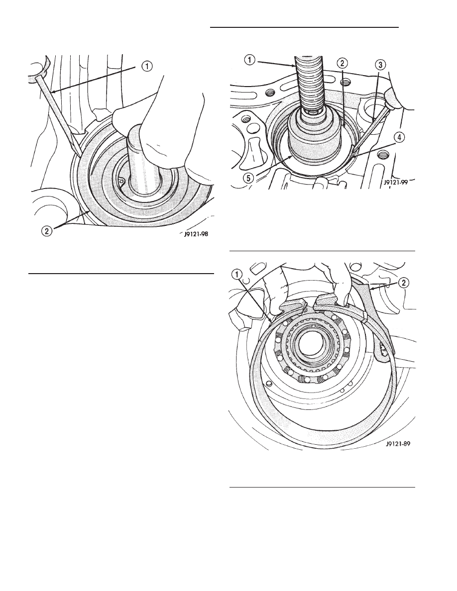
Fig. 43 Front Servo Piston

1 - USE SUITABLE TOOL TO HELP SEAT PISTON RING
2 - FRONT SERVO PISTON

Fig. 44 Front Servo Rod Guide And Snap-Ring

1 - C-CLAMP
2 - ROD GUIDE
3 - SMALL SCREWDRIVER
4 - ROD GUIDE SNAP-RING
5 - TOOL SP-5560

Fig. 45 Rear Band And Link

1 - REAR BAND
2 - BAND LINK

21 - 292

AUTOMATIC TRANSMISSION - 46RE

AN

AUTOMATIC TRANSMISSION - 46RE (Continued)

(6) Insert band reaction pin part way into case and

band link (Fig. 48).

(7) Install rear band adjusting lever, reaction lever,

and strut (Fig. 49). Be sure levers and strut are
aligned and engaged before seating band reaction pin
in case.

Fig. 46 Low-Reverse Drum

1 - LOW-REVERSE DRUM
2 - REAR BAND LINK
3 - HUB OF OVERDRIVE PISTON RETAINER

Fig. 47 Low-Reverse Drum Snap-Ring

1 - LOW-REVERSE DRUM
2 - TABBED WASHER
3 - SNAP-RING

Fig. 48 Rear Band Reaction Pin

1 - REACTION PIN
2 - BAND LINK
3 - REAR BAND
4 - O-RINGS

Fig. 49 Rear Band Levers And Strut

1 - ADJUSTING SCREW AND NUT
2 - ADJUSTING LEVER
3 - REACTION LEVER
4 - STRUT

AN

AUTOMATIC TRANSMISSION - 46RE

21 - 293

AUTOMATIC TRANSMISSION - 46RE (Continued)

PLANETARY GEARTRAIN, FRONT/REAR CLUTCH,
AND FRONT BAND

(1) Remove Alignment Shaft 6227-2, if installed

previously.

(2) Install assembled intermediate shaft and plan-

etary geartrain (Fig. 50). Support shaft carefully dur-
ing installation. Do not allow shaft bearing/bushing
surfaces to become nicked or scratched.

(3) Lubricate intermediate shaft thrust plate with

petroleum jelly and install plate on shaft pilot hub
(Fig. 51).

(4) Check input shaft front seal rings, fiber thrust

washer and rear seal ring (Fig. 52). Be ends of rear
seal ring are hooked together and the square cut
ends of front seal rings are firmly seated against
each other. Lubricate seal rings with petroleum jelly
after checking them.

(5) Assemble front and rear clutches (Fig. 53).

Align lugs on front clutch discs. Mount front clutch
on rear clutch. Turn front clutch retainer back and
forth until front clutch discs are fully seated on rear
clutch splined hub.

Fig. 50 Intermediate Shaft And Planetary Geartrain

1 - INTERMEDIATE SHAFT AND PLANETARY GEARTRAIN
ASSEMBLY

Fig. 51 Intermediate Shaft Thrust Plate

1 - SHAFT THRUST PLATE
2 - INTERMEDIATE SHAFT PILOT HUB

Fig. 52 Input Shaft Seal Rings And Thrust Washer

1 - TORLON® FRONT SEAL RINGS
2 - INPUT SHAFT
3 - REAR SEAL RING
4 - THRUST WASHER

21 - 294

AUTOMATIC TRANSMISSION - 46RE

AN

AUTOMATIC TRANSMISSION - 46RE (Continued)

(6) Install intermediate shaft thrust washer in hub

of rear clutch retainer (Fig. 54). Use petroleum jelly
to hold washer in place. Position washer so grooves
are facing outward. Washer only fits one way in
clutch retainer hub.

(7) Place transmission case in upright position, or

place blocks under front end of transmission repair
stand to tilt case rearward. This makes it easier to
install front/rear clutch assembly.

(8) Align discs in rear clutch. Then install and

engage assembly in front planetary and driving shell
(Fig. 55). Turn clutch retainers back and forth until
both clutches are seated.

(9) Position front band lever in case and over servo

rod guide. Then install front band lever pin in case
and slide it through lever.

(10) Coat threads of front band pin access plug

with sealer and install it in case. Tighten plug to 17
N·m (13 ft. lbs.) torque.

(11) Slide front band over front clutch retainer and

install front band strut and anchor (Fig. 56).

(12) Tighten front band adjusting screw until band

is tight on clutch retainer. This will hold clutches in
place while oil pump is being installed. Verify that
front/rear clutch assembly is still properly seated
before tightening band.

Fig. 53 Assembling Front And Rear Clutches

1 - FRONT CLUTCH ASSEMBLY
2 - REAR CLUTCH ASSEMBLY
3 - REAR CLUTCH SPLINED HUB

Fig. 54 Intermediate Shaft Thrust Washer

1 - BE SURE WASHER GROOVES FACE OUT AS SHOWN
2 - REAR CLUTCH RETAINER HUB
3 - OUTPUT SHAFT THRUST WASHER

Fig. 55 Front/Rear Clutch Assemblies

1 - FRONT AND REAR CLUTCH ASSEMBLIES

AN

AUTOMATIC TRANSMISSION - 46RE

21 - 295

AUTOMATIC TRANSMISSION - 46RE (Continued)


Content   ..  660  661  662  663   ..