Dodge Dakota (R1). Manual - part 660


  Index      Dodge     Dodge Dakota (R1) - service repair manual 2000 year


Search            


Content   ..  658  659  660  661   ..


Dodge Dakota (R1). Manual - part 660


(7) Remove the transmission range sensor.
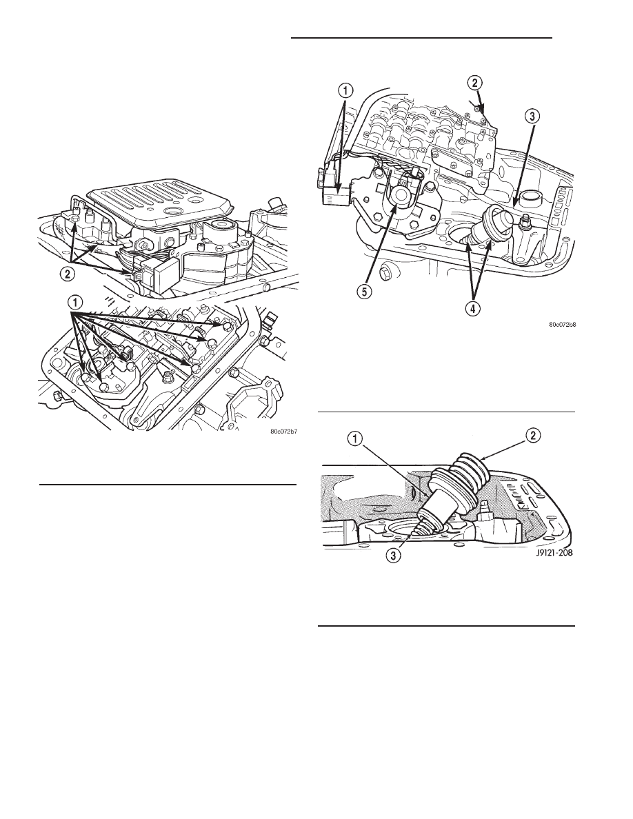
(8) Remove hex head bolts attaching valve body to

transmission case (Fig. 17). A total of 10 bolts are
used. Note different bolt lengths for assembly refer-
ence.

(9) Remove valve body assembly. Push valve body

harness connector out of case. Then work park rod
and valve body out of case (Fig. 18).

(10) Remove accumulator outer spring, piston and

inner spring (Fig. 19). Note position of piston and
springs for assembly reference. Remove and discard
piston seals if worn or cut.

(11) Remove pump oil seal with suitable pry tool or

slide-hammer mounted screw.

(12) Remove front band lever pin access plug (Fig.

20). Use square end of 1/4 in. drive extension to
remove plug as shown.

Fig. 17 Valve Body Bolt Locations

1 - VALVE BODY BOLTS
2 - VALVE BODY BOLTS

Fig. 18 Valve Body Removal

1 - GOVERNOR PRESSURE SENSOR
2 - VALVE BODY
3 - PARK ROD
4 - ACCUMULATOR PISTON
5 - GOVERNOR PRESSURE SOLENOID

Fig. 19 Accumulator Component Removal

1 - ACCUMULATOR PISTON
2 - OUTER SPRING
3 - INNER SPRING

21 - 284

AUTOMATIC TRANSMISSION - 46RE

AN

AUTOMATIC TRANSMISSION - 46RE (Continued)

(13) Remove oil pump and reaction shaft support

assembly as follows:

(a) Tighten front band adjusting screw until

band is tight around front clutch retainer (Fig. 21).
This will prevent retainer from coming out with
pump and possibly damaging clutch or pump com-
ponents.

(b) Remove oil pump bolts.
(c) Thread Slide Hammer Tools C-3752 into

threaded holes in flange of oil pump housing (Fig.
22).

(d) Remove oil pump and reaction shaft support

by bumping slide hammers outward alternately to
pull pump from case (Fig. 23).
(14) Remove oil pump gasket (Fig. 24). Note gas-

ket position in case for assembly reference.

(15) Loosen front band adjusting screw until band

is completely loose.

(16) Remove front band strut and anchor (Fig. 25).
(17) Squeeze front band together slightly and slide

band over front clutch retainer and out of case (Fig.
26).

Fig. 20 Front Band Lever Pin Access Plug

1 - FRONT BAND REACTION PIN ACCESS PLUG
2 - 1/4 DRIVE EXTENSION AND RATCHET

Fig. 21 Tightening Front Band To Hold Front Clutch

In Place

1 - LOCK-NUT
2 - FRONT BAND ADJUSTER

Fig. 22 Oil Pump Removal Tools

1 - PUMP HOUSING
2 - SLIDE HAMMER TOOLS (THREAD INTO PUMP HOUSING)

AN

AUTOMATIC TRANSMISSION - 46RE

21 - 285

AUTOMATIC TRANSMISSION - 46RE (Continued)

(18) Remove front and rear clutch assemblies as a

unit (Fig. 27).

(19) Remove front band reaction pin and lever.

Start pin through lever and out of case bore with
drift or punch. Then use pencil magnet to withdraw
pin completely (Fig. 28).

(20) Remove intermediate shaft thrust washer. Tri-

angular shaped washer will either be on shaft pilot
hub or in rear clutch retainer (Fig. 29).

Fig. 23 Oil Pump Removal

1 - OIL PUMP AND REACTION SHAFT SUPPORT

Fig. 24 Oil Pump Gasket

1 - OIL PUMP GASKET

Fig. 25 Front Band Linkage

1 - LEVER
2 - STRUT
3 - ANCHOR
4 - FRONT BAND

Fig. 26 Front Band Removal

1 - FRONT BAND
2 - FRONT CLUTCH RETAINER

21 - 286

AUTOMATIC TRANSMISSION - 46RE

AN

AUTOMATIC TRANSMISSION - 46RE (Continued)

(21) Remove thrust plate from intermediate shaft

hub (Fig. 30).

(22) Remove intermediate shaft-planetary geartrain

assembly (Fig. 31).

(23) If overdrive unit is not to be serviced, install

Alignment Shaft 6227-2 into the overdrive unit to
prevent misalignment of the overdrive clutches dur-
ing service of main transmission components.

(24) Loosen rear band locknut and loosen adjust-

ing screw 3-4 turns.

(25) Remove snap-ring that retains low-reverse

drum on overdrive piston retainer hub (Fig. 32).

(26) Slide low-reverse drum and thrust washer off

piston retainer hub and out of rear band (Fig. 33).

(27) Note that overrunning clutch race will remain

on splines of low-reverse drum after removal (Fig.
34). The race is a permanent press fit on the
hub splines. Do not attempt to remove the race.

Fig. 27 Removing Front/Rear Clutch Assemblies

1 - FRONT AND REAR CLUTCH ASSEMBLIES

Fig. 28 Front Band Lever And Pin

1 - BAND LEVER
2 - USE PENCIL MAGNET TO REMOVE REACTION PIN

Fig. 29 Intermediate Shaft Thrust Washer

1 - THRUST WASHER
2 - INTERMEDIATE SHAFT PILOT HUB

Fig. 30 Intermediate Shaft Thrust Plate

1 - SHAFT THRUST PLATE
2 - INTERMEDIATE SHAFT PILOT HUB

AN

AUTOMATIC TRANSMISSION - 46RE

21 - 287

AUTOMATIC TRANSMISSION - 46RE (Continued)


Content   ..  658  659  660  661   ..