Dodge Dakota (R1). Manual - part 663


  Index      Dodge     Dodge Dakota (R1) - service repair manual 2000 year


Search            


Content   ..  661  662  663  664   ..


Dodge Dakota (R1). Manual - part 663


OIL PUMP

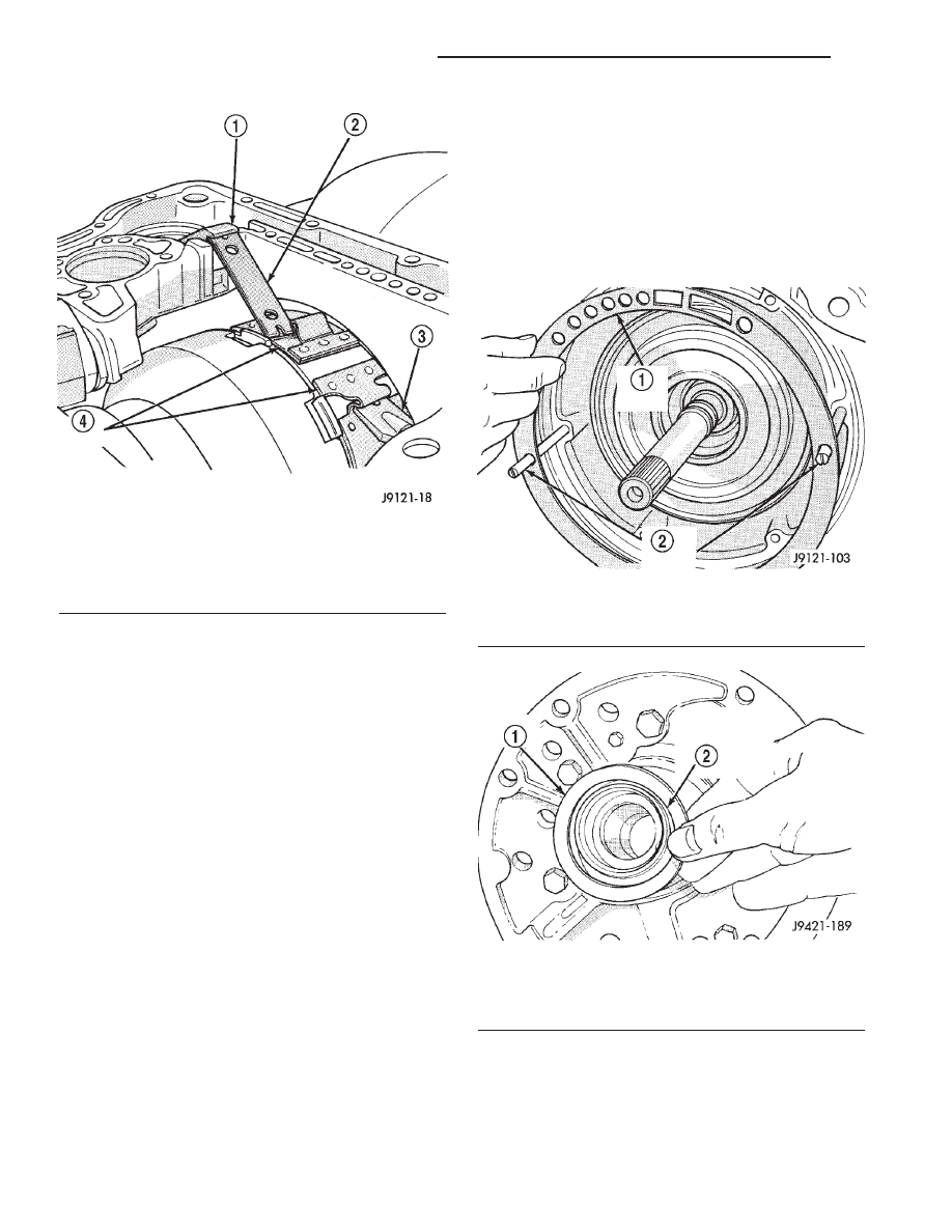
(1) Install oil pump Pilot Studs C-3288-B in case

(Fig. 57).

(2) Install new oil pump gasket on pilot studs and

seat it in case. Be sure gasket is properly aligned
with fluid passages in case (Fig. 57).

(3) Coat front clutch fiber thrust washer with

petroleum jelly to hold it in place. Then install
washer over reaction shaft hub and seat it on pump
(Fig. 58).

CAUTION: The thrust washer bore (I.D.), is cham-
fered on one side. Make sure the chamfered side is
installed so it faces the pump.

(4) Check seal rings on reaction shaft support. Be

sure rings are hooked together correctly. Also be sure
fiber thrust washer is in position (Fig. 59). Use extra
petroleum jelly to hold washer in place if necessary.

(5) Lubricate

oil

pump

seals

with

petroleum

Mopar® ATF +4, type 9602.

(6) Mount oil pump on pilot studs and slide pump

into case opening (Fig. 60). Work pump into case by
hand. Do not use a mallet or similar tools to seat
pump.

(7) Remove pilot studs and install oil pump bolts.

Tighten pump bolts alternately and evenly to fully
seat pump in case. Then final-tighten pump bolts to
20 N·m (15 ft. lbs.) torque.

(8) Verify correct installation. Rotate input and

intermediate shafts and check for bind. If bind exists,
components are either mis-assembled, or not seated.
Disassemble and correct as necessary before proceed-
ing.

Fig. 56 Front Band And Linkage

1 - LEVER
2 - STRUT
3 - ANCHOR
4 - FRONT BAND

Fig. 57 Oil Pump Gasket And Pilot Studs

1 - OIL PUMP GASKET
2 - PILOT STUDS C-3288-B

Fig. 58 Front Clutch Thrust Washer

1 - THRUST WASHER
2 - CHAMFERED SIDE OF WASHER BORE GOES TOWARD
PUMP

21 - 296

AUTOMATIC TRANSMISSION - 46RE

AN

AUTOMATIC TRANSMISSION - 46RE (Continued)

INPUT SHAFT END PLAY CHECK

NOTE: Overdrive unit must be installed in order to
correctly measure the input shaft end-play.

(1) Measure input shaft end play (Fig. 61).

NOTE: If end play is incorrect, transmission is
incorrectly assembled, or reaction shaft thrust
washer is incorrect. The reaction shaft thrust
washer is selective.

(a) Attach Adapter 8266-5 to Handle 8266-8.
(b) Attach

dial

indicator

C-3339

to

Handle

8266-8.

(c) Install the assembled tool onto the input

shaft of the transmission and tighten the retaining
screw on Adapter 8266-5 to secure it to the input
shaft.

(d) Position the dial indicator plunger against a

flat spot on the oil pump and zero the dial indica-
tor.

(e) Move input shaft in and out and record read-

ing. End play should be 0.86 - 2.13 mm (0.034 -
0.084 in.). Adjust as necessary.

Fig. 59 Reaction Shaft Seal Ring And Thrust Washer

1 - SEAL RINGS
2 - REACTION SHAFT SUPPORT
3 - THRUST WASHER (FIBER)

Fig. 60 Oil Pump

1 - SEAT OIL PUMP IN CASE BY HAND
2 - REMOVE PILOT STUDS WHEN PUMP IS SEATED

Fig. 61 Checking Input Shaft End Play

1 - TOOL 8266-8
2 - TOOL 8266-5
3 - TOOL C-3339

AN

AUTOMATIC TRANSMISSION - 46RE

21 - 297

AUTOMATIC TRANSMISSION - 46RE (Continued)

ACCUMULATOR, VALVE BODY, OIL PAN, AND
TORQUE CONVERTER

(1) Install accumulator inner spring, piston and

outer spring (Fig. 62).

(2) Install new valve body manual shaft seal in

case (Fig. 63). Lubricate seal lip and manual shaft
with petroleum jelly. Start seal over shaft and into
case. Seat seal with 15/16 inch, deep well socket.

(3) Install valve body as follows:

(a) Start park rod into park pawl. If rod will not

slide past park pawl, pawl is engaged in park gear.
Rotate overdrive output shaft with suitable size 12
point socket; this will free pawl and allow rod to
engage.

(b) Align and seat valve body on case. Be sure

manual lever shaft and overdrive connector are
fully seated in case.

(c) Install and start all valve body attaching

bolts by hand. Then tighten bolts evenly, in a diag-
onal pattern to 12 N·m (105 in. lbs.) torque. Do
not overtighten valve body bolts. This could
result in distortion and cross leakage after
installation.
.

CAUTION: It is possible for the park rod to displace
into a cavity just above the pawl sprag during
installation. Make sure the rod is actually engaged
in the pawl and has not displaced into this cavity.

(4) Install new filter on valve body. Tighten filter

screws to 4 N·m (35 in. lbs.).

(5) Install the transmission range sensor.

CAUTION: If the condition of the transmission
before the overhaul procedure caused excessive
metallic or fiber contamination in the fluid, replace
the torque converter and reverse flush the cooler(s)
and cooler lines. Fluid contamination and transmis-
sion failure can result if not done.

(6) Install torque converter. Use C-clamp or metal

strap to hold converter in place for installation.

BAND ADJUSTMENT AND FINAL

(1) Adjust front and rear bands as follows:

(a) Loosen locknut on each band adjusting screw

4-5 turns.

(b) Tighten both adjusting screws to 8 N·m (72

in. lbs.).

(c) Back off front band adjusting screw 2-7/8

turns.

(d) Back off rear band adjusting screw 2 turns.
(e) Hold each adjusting screw in position and

tighten locknut to 34 N·m (25 ft. lbs.) torque.
(2) Install magnet in oil pan. Magnet seats on

small protrusion at corner of pan.

(3) Position new oil pan gasket on case and install

oil pan. Tighten pan bolts to 17 N·m (13 ft. lbs.).

(4) Install throttle valve and shift selector levers

on valve body manual lever shaft.

(5) Apply small quantity of dielectric grease to ter-

minal pins of solenoid case connector and transmis-
sion range sensor.

(6) Fill

transmission

with

recommended

fluid.

Refer to Service Procedures section of this group.

INSTALLATION

(1) Check torque converter hub and hub drive

notches for sharp edges burrs, scratches, or nicks.
Polish the hub and notches with 320/400 grit paper
and crocus cloth if necessary. The hub must be
smooth to avoid damaging pump seal at installation.

(2) Lubricate oil pump seal lip with transmission

fluid.

(3) Lubricate converter pilot hub pocket in the rear

of the crankshaft with a light coating of Mopar®
High Temp Grease.

(4) Align and install converter in oil pump.

Fig. 62 Accumulator Piston And Springs

1 - ACCUMULATOR PISTON
2 - OUTER SPRING
3 - INNER SPRING

Fig. 63 Manual Lever Shaft Seal

1 - 15/16'' SOCKET
2 - SEAL

21 - 298

AUTOMATIC TRANSMISSION - 46RE

AN

AUTOMATIC TRANSMISSION - 46RE (Continued)

(5) Carefully insert converter in oil pump. Then

rotate converter back and forth until fully seated in
pump gears.

(6) Check converter seating with steel scale and

straightedge (Fig. 64). Surface of converter lugs
should be 1/2 in. to rear of straightedge when con-
verter is fully seated.

(7) Temporarily secure converter with wedge tool

or C-clamp.

(8) Position transmission on jack and secure it

with chains.

(9) Check

condition

of

converter

driveplate.

Replace the plate if cracked, distorted or damaged.
Also be sure transmission dowel pins are seated in
engine block and protrude far enough to held trans-
mission in alignment.

(10) Raise transmission and align converter with

drive plate and converter housing with engine block.

(11) Move transmission forward. Then raise, lower

or tilt transmission to align converter housing with
engine block dowels.

(12) Carefully work transmission forward and over

engine block dowels until converter hub is seated in
crankshaft.

(13) Install bolts attaching converter housing to

engine.

(14) Install transfer case, if necessary.
(15) Install rear support. Then lower transmission

onto crossmember and install bolts attaching trans-
mission mount to crossmember.

(16) Install new plastic retainer grommet on any

shift linkage rod or lever that was disconnected.
Grommets should not be reused.

(17) Connect gearshift and throttle cable to trans-

mission.

(18) Connect wires to the transmission range sen-

sor, transmission solenoid case connector, and oxygen
sensor. Be sure that all transmission harnesses are
properly routed.

CAUTION: It is essential that correct length bolts be
used to attach the converter to the driveplate. Bolts
that are too long will damage the clutch surface
inside the converter.

(19) Install torque converter-to-driveplate bolts.

Tighten bolts to 31 N·m (270 in. lbs.).

(20) Raise engine slightly.
(21) Loosen bolts attaching engine-to-transmission

brackets to each side of the engine block.

(22) Install converter housing access cover.
(23) Install bolts attaching engine-to-transmission

brackets to transmission.

(24) Tighten bolts attaching engine-to-transmis-

sion brackets to each side of the engine block.

(25) Lower engine.
(26) Install bolt and nut attaching each engine-to-

transmission bracket to the motor mounts.

(27) Remove engine support.
(28) Install bolts to hold engine-to-transmission

brackets to the front axle, if equipped.

(29) Install starter motor (Refer to 8 - ELECTRI-

CAL/STARTING/STARTER MOTOR - INSTALLA-
TION) and cooler line bracket.

(30) Connect cooler lines to transmission.
(31) Install transmission fill tube. Install new seal

on tube before installation.

(32) Install exhaust components.
(33) Align and connect propeller shaft(s). (Refer to

3 - DIFFERENTIAL & DRIVELINE/PROPELLER
SHAFT/PROPELLER SHAFT - INSTALLATION)

(34) Install rear skid plate, if equipped.
(35) Adjust gearshift linkage and throttle valve

cable if necessary.

(36) Install front skid plate, if equipped.
(37) Lower vehicle.
(38) Fill transmission with Mopar® ATF +4, Type

9602 fluid.

Fig. 64 Checking Converter Seating - Typical

1 - SCALE
2 - STRAIGHTEDGE

AN

AUTOMATIC TRANSMISSION - 46RE

21 - 299

AUTOMATIC TRANSMISSION - 46RE (Continued)


Content   ..  661  662  663  664   ..