Dodge Dakota (R1). Manual - part 656


  Index      Dodge     Dodge Dakota (R1) - service repair manual 2000 year


Search            


Content   ..  654  655  656  657   ..


Dodge Dakota (R1). Manual - part 656


Test Four - Transmission In Reverse

NOTE: This test checks pump output, pressure reg-
ulation and the front clutch and rear servo circuits.
Use 300 psi Test Gauge C-3293-SP for this test.

(1) Leave vehicle on hoist and leave gauge C-3292

in place at accumulator port.

(2) Move 300 psi Gauge C-3293-SP back to rear

servo port.

(3) Have helper start and run engine at 1600 rpm

for test.

(4) Move transmission shift lever four detents

rearward from full forward position. This is Reverse
range.

(5) Move transmission throttle lever fully forward

then fully rearward and note reading at Gauge
C-3293-SP.

(6) Pressure should be 145 - 175 psi (1000-1207

kPa) with throttle lever forward and increase to 230 -
280 psi (1586-1931 kPa) as lever is gradually moved
rearward.

Test Five - Governor Pressure

NOTE: This test checks governor operation by mea-
suring governor pressure response to changes in
vehicle speed. It is usually not necessary to check
governor operation unless shift speeds are incor-
rect or if the transmission will not downshift. The
test should be performed on the road or on a hoist
that will allow the rear wheels to rotate freely.

(1) Move 100 psi Test Gauge C-3292 to governor

pressure port.

(2) Move transmission shift lever two detents rear-

ward from full forward position. This is D range.

(3) Have helper start and run engine at curb idle

speed. Then firmly apply service brakes so wheels
will not rotate.

(4) Note governor pressure:
• Governor pressure should be no more than 20.6

kPa (3 psi) at curb idle speed and wheels not rotat-
ing.

• If pressure exceeds 20.6 kPa (3 psi), a fault

exists in governor pressure control system.

(5) Release brakes, slowly increase engine speed,

and observe speedometer and pressure test gauge (do
not exceed 30 mph on speedometer). Governor pres-
sure should increase in proportion to vehicle speed.
Or approximately 6.89 kPa (1 psi) for every 1 mph.

(6) Governor pressure rise should be smooth and

drop back to no more than 20.6 kPa (3 psi), after
engine returns to curb idle and brakes are applied to
prevent wheels from rotating.

(7) Compare results of pressure test with analysis

chart.

Test Six - Transmission In Overdrive Fourth Gear

NOTE: This test checks line pressure at the over-
drive clutch in fourth gear range. Use 300 psi Test
Gauge C-3293-SP for this test. The test should be
performed on the road or on a chassis dyno.

(1) Remove tachometer; it is not needed for this

test.

(2) Move 300 psi Gauge to overdrive clutch pres-

sure test port. Then remove other gauge and reinstall
test port plug.

(3) Lower vehicle.
(4) Turn OD switch on.
(5) Secure test gauge so it can be viewed from

drivers seat.

(6) Start engine and shift into D range.
(7) Increase vehicle speed gradually until 3-4 shift

occurs and note gauge pressure.

(8) Pressure should be 469-496 kPa (68-72 psi)

with closed throttle and increase to 620-827 kPa (90-
120 psi) at 1/2 to 3/4 throttle. Note that pressure can
increase to around 896 kPa (130 psi) at full throttle.

(9) Return to shop or move vehicle off chassis

dyno.

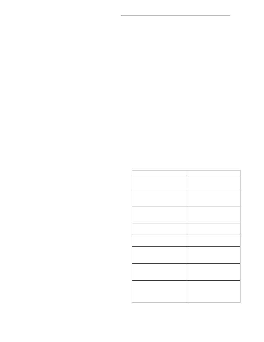
PRESSURE TEST ANALYSIS CHART

TEST CONDITION

INDICATION

Line pressure OK during
any one test

Pump and regulator
valve OK

Line pressure OK in R
but low in D, 2, 1

Leakage in rear clutch
area (seal rings, clutch
seals)

Pressure low in D Fourth
Gear Range

Overdrive clutch piston
seal, or check ball
problem

Pressure OK in 1, 2 but
low in D3 and R

Leakage in front clutch
area

Pressure OK in 2 but low
in R and 1

Leakage in rear servo

Front servo pressure in 2

Leakage in servo; broken
servo ring or cracked
servo piston

Pressure low in all
positions

Clogged filter, stuck
regulator valve, worn or
faulty pump, low oil level

Governor pressure too
high at idle speed

Governor pressure
solenoid valve system
fault. Refer to diagnostic
book.

21 - 268

AUTOMATIC TRANSMISSION - 46RE

AN

AUTOMATIC TRANSMISSION - 46RE (Continued)

TEST CONDITION

INDICATION

Governor pressure low at
all mph figures

Faulty governor pressure
solenoid, transmission
control module, or
governor pressure
sensor

Lubrication pressure low
at all throttle positions

Clogged fluid cooler or
lines, seal rings leaking,
worn pump bushings,
pump, clutch retainer, or
clogged filter.

Line pressure high

Output shaft plugged,
sticky regulator valve

Line pressure low

Sticky regulator valve,
clogged filter, worn pump

DIAGNOSIS AND TESTING - AIR TESTING
TRANSMISSION CLUTCH AND BAND
OPERATION

Air-pressure testing can be used to check transmis-

sion front/rear clutch and band operation. The test
can be conducted with the transmission either in the
vehicle or on the work bench, as a final check, after
overhaul.

Air-pressure testing requires that the oil pan and

valve body be removed from the transmission. The
servo and clutch apply passages are shown (Fig. 10).

Front Clutch Air Test

Place one or two fingers on the clutch housing and

apply air pressure through front clutch apply pas-
sage. Piston movement can be felt and a soft thump
heard as the clutch applies.

Rear Clutch Air Test

Place one or two fingers on the clutch housing and

apply air pressure through rear clutch apply passage.
Piston movement can be felt and a soft thump heard
as the clutch applies.

Front Servo Air Test

Apply air pressure to the front servo apply pas-

sage. The servo rod should extend and cause the
band to tighten around the drum. Spring pressure
should release the servo when air pressure is
removed.

Rear Servo Air Test

Apply air pressure to the rear servo apply passage.

The servo rod should extend and cause the band to
tighten around the drum. Spring pressure should
release the servo when air pressure is removed.

DIAGNOSIS AND TESTING - CONVERTER
HOUSING FLUID LEAK

When diagnosing converter housing fluid leaks,

two items must be established before repair.

(1) Verify that a leak condition actually exists.
(2) Determined the true source of the leak.
Some suspected converter housing fluid leaks may

not be leaks at all. They may only be the result of
residual fluid in the converter housing, or excess
fluid spilled during factory fill or fill after repair.
Converter

housing

leaks

have

several

potential

sources. Through careful observation, a leak source
can be identified before removing the transmission
for repair. Pump seal leaks tend to move along the
drive hub and onto the rear of the converter. Pump
body leaks follow the same path as a seal leak (Fig.
11). Pump vent or pump attaching bolt leaks are gen-
erally deposited on the inside of the converter hous-
ing and not on the converter itself (Fig. 11). Pump
o-ring or gasket leaks usually travel down the inside
of the converter housing. Front band lever pin plug
leaks are generally deposited on the housing and not
on the converter.

Fig. 10 Air Pressure Test Passages

1 - LINE PRESSURE TO ACCUMULATOR
2 - REAR SERVO APPLY
3 - FRONT SERVO APPLY
4 - FRONT SERVO RELEASE
5 - PUMP SUCTION
6 - PUMP PRESSURE
7 - FRONT CLUTCH APPLY
8 - REAR CLUTCH APPLY
9 - TO TORQUE CONVERTOR
10 - TO COOLER
11 - FROM TORQUE CONVERTER

AN

AUTOMATIC TRANSMISSION - 46RE

21 - 269

AUTOMATIC TRANSMISSION - 46RE (Continued)

TORQUE CONVERTER LEAK POINTS

Possible sources of converter leaks are:
(1) Leaks at the weld joint around the outside

diameter weld (Fig. 12).

(2) Leaks at the converter hub weld (Fig. 12).

CONVERTER HOUSING AREA LEAK CORRECTION

(1) Remove converter.
(2) Tighten front band adjusting screw until band

is tight around front clutch retainer. This prevents
front/rear clutches from coming out when oil pump is
removed.

(3) Remove oil pump and remove pump seal.

Inspect pump housing drainback and vent holes for
obstructions. Clear holes with solvent and wire.

(4) Inspect pump bushing and converter hub. If

bushing is scored, replace it. If converter hub is
scored, either polish it with crocus cloth or replace
converter.

(5) Install new pump seal, O-ring, and gasket.

Replace oil pump if cracked, porous or damaged in
any way. Be sure to loosen the front band before
installing the oil pump, damage to the oil pump seal
may occur if the band is still tightened to the front
clutch retainer.

(6) Loosen kickdown lever pin access plug three

turns. Apply Loctite™ 592, or Permatex® No. 2 to
plug threads and tighten plug to 17 N·m (150 in. lbs.)
torque.

(7) Adjust front band.
(8) Lubricate pump seal and converter hub with

transmission fluid or petroleum jelly and install con-
verter.

(9) Install transmission and converter housing

dust shield.

(10) Lower vehicle.

DIAGNOSIS AND TESTING - DIAGNOSIS
CHARTS

The diagnosis charts provide additional reference

when diagnosing a transmission fault. The charts
provide general information on a variety of transmis-
sion, overdrive unit and converter clutch fault condi-
tions.

The hydraulic flow charts in the Schematics and

Diagrams section of this group, outline fluid flow and
hydraulic circuitry. Circuit operation is provided for
PARK,

NEUTRAL,

FIRST,

SECOND,

THIRD,

FOURTH, MANUAL FIRST, MANUAL SECOND,
and REVERSE gear ranges. Normal working pres-
sures are also supplied for each of the gear ranges.

Fig. 11 Converter Housing Leak Paths

1 - PUMP SEAL
2 - PUMP VENT
3 - PUMP BOLT
4 - PUMP GASKET
5 - CONVERTER HOUSING
6 - CONVERTER
7 - REAR MAIN SEAL LEAK

Fig. 12 Converter Leak Points - Typical

1 - OUTSIDE DIAMETER WELD
2 - TORQUE CONVERTER HUB WELD
3 - STARTER RING GEAR
4 - LUG

21 - 270

AUTOMATIC TRANSMISSION - 46RE

AN

AUTOMATIC TRANSMISSION - 46RE (Continued)

DIAGNOSIS CHARTS

CONDITION

POSSIBLE CAUSES

CORRECTION

HARSH ENGAGEMENT
(FROM NEUTRAL TO
DRIVE OR REVERSE)

1. Fluid Level Low.

1. Add Fluid

2. Throttle Linkage Mis-adjusted.

2. Adjust linkage - setting may be too long.

3. Mount and Driveline Bolts Loose.

3. Check engine mount, transmission
mount, propeller shaft, rear spring to body
bolts, rear control arms, crossmember and
axle bolt torque. Tighten loose bolts and
replace missing bolts.

4. U-Joint Worn/Broken.

4. Remove propeller shaft and replace
U-Joint.

5. Axle Backlash Incorrect.

5. Check per Service Manual. Correct as
needed.

6. Hydraulic Pressure Incorrect.

6. Check pressure. Remove, overhaul or
adjust valve body as needed.

7. Band Mis-adjusted.

7. Adjust rear band.

8. Valve Body Check Balls Missing.

8. Inspect valve body for proper check ball
installation.

9. Axle Pinion Flange Loose.

9. Replace nut and check pinion threads
before installing new nut. Replace pinion
gear if threads are damaged.

10. Clutch, band or planetary
component damaged.

10. Remove, disassemble and repair
transmission as necessary.

11. Converter Clutch Faulty.

11. Replace converter and flush cooler and
line before installing new converter.

DELAYED ENGAGEMENT
(FROM NEUTRAL TO
DRIVE OR REVERSE)

1. Fluid Level Low.

1. Correct level and check for leaks.

2. Filter Clogged.

2. Change filter.

3. Gearshift Linkage Mis-adjusted.

3. Adjust linkage and repair linkage if worn
or damaged.

4. Torque Converter Drain Back (Oil
drains from torque converter into
transmission sump).

4. If vehicle moves normally after 5
seconds after shifting into gear, no repair is
necessary. If longer, inspect pump bushing
for wear. Replace pump house.

5. Rear Band Mis-adjusted.

5. Adjust band.

6. Valve Body Filter Plugged.

6. Replace fluid and filter. If oil pan and old
fluid were full of clutch disc material and/or
metal particles, overhaul will be necessary.

7. Oil Pump Gears Worn/Damaged.

7. Remove transmission and replace oil
pump.

8. Governor Circuit and Solenoid
Valve Electrical Fault.

8. Test with DRB® scan tool and repair as
required.

9. Hydraulic Pressure Incorrect.

9. Perform pressure test, remove
transmission and repair as needed.

10. Reaction Shaft Seal Rings
Worn/Broken.

10. Remove transmission, remove oil pump
and replace seal rings.

11. Rear Clutch/Input Shaft, Rear
Clutch Seal Rings Damaged.

11. Remove and disassemble transmission
and repair as necessary.

12. Regulator Valve Stuck.

12. Clean.

13. Cooler Plugged.

13. Transfer case failure can plug cooler.

AN

AUTOMATIC TRANSMISSION - 46RE

21 - 271

AUTOMATIC TRANSMISSION - 46RE (Continued)


Content   ..  654  655  656  657   ..