Dodge Dakota (R1). Manual - part 654


  Index      Dodge     Dodge Dakota (R1) - service repair manual 2000 year


Search            


Content   ..  652  653  654  655   ..


Dodge Dakota (R1). Manual - part 654


PARK POWERFLOW

As the engine is running and the crankshaft is

rotating, the flexplate and torque converter, which
are also bolted to it, are all rotating in a clockwise
direction as viewed from the front of the engine. The
notched hub of the torque converter is connected to
the oil pump’s internal gear, supplying the transmis-
sion with oil pressure. As the converter turns, it
turns the input shaft in a clockwise direction. As the
input shaft is rotating, the front clutch hub-rear
clutch retainer and all their associated parts are also
rotating, all being directly connected to the input
shaft. The power flow from the engine through the
front clutch hub and rear clutch retainer stops at the
rear clutch retainer. Therefore, no power flow to the
output shaft occurs because no clutches are applied.
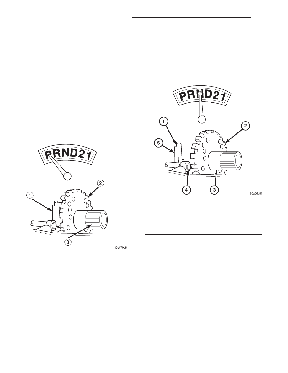
The only mechanism in use at this time is the park-
ing sprag (Fig. 3), which locks the parking gear on
the output shaft to the transmission case.

NEUTRAL POWERFLOW

With the gear selector in the NEUTRAL position

(Fig. 4), the power flow of the transmission is essen-
tially the same as in the park position. The only
operational difference is that the parking sprag has
been disengaged, unlocking the output shaft from the
transmission case and allowing it to move freely.

Fig. 3 Park Powerflow

1 - PAWL ENGAGED FOR PARK
2 - PARK SPRAG
3 - OUTPUT SHAFT

Fig. 4 Neutral Powerflow

1 - PAWL DISENGAGED FOR NEUTRAL
2 - PARK SPRAG
3 - OUTPUT SHAFT
4 - CAM
5 - PAWL

21 - 260

AUTOMATIC TRANSMISSION - 46RE

AN

AUTOMATIC TRANSMISSION - 46RE (Continued)

REVERSE POWERFLOW

When

the

gear

selector

is

moved

into

the

REVERSE position (Fig. 5), the front clutch and the
rear band are applied. With the application of the
front clutch, engine torque is applied to the sun gear,
turning it in a clockwise direction. The clockwise
rotation of the sun gear causes the rear planet pin-
ions to rotate against engine rotation in a counter-
clockwise direction. The rear band is holding the low
reverse drum, which is splined to the rear carrier.
Since the rear carrier is being held, the torque from

the planet pinions is transferred to the rear annulus
gear, which is splined to the output shaft. The output
shaft in turn rotates with the annulus gear in a
counterclockwise direction giving a reverse gear out-
put. The entire transmission of torque is applied to
the rear planetary gearset only. Although there is
torque input to the front gearset through the sun
gear, no other member of the gearset is being held.
During the entire reverse stage of operation, the
front planetary gears are in an idling condition.

Fig. 5 Reverse Powerflow

1 - FRONT CLUTCH ENGAGED

5 - OUTPUT SHAFT

2 - OUTPUT SHAFT

6 - INPUT SHAFT

3 - LOW/REVERSE BAND APPLIED

7 - FRONT CLUTCH ENGAGED

4 - INPUT SHAFT

8 - LOW/REVERSE BAND APPLIED

AN

AUTOMATIC TRANSMISSION - 46RE

21 - 261

AUTOMATIC TRANSMISSION - 46RE (Continued)

FIRST GEAR POWERFLOW

When the gearshift lever is moved into the DRIVE

position the transmission goes into first gear (Fig. 6).
As soon as the transmission is shifted from PARK or
NEUTRAL to DRIVE, the rear clutch applies, apply-
ing the rear clutch pack to the front annulus gear.
Engine torque is now applied to the front annulus
gear turning it in a clockwise direction. With the
front annulus gear turning in a clockwise direction, it
causes the front planets to turn in a clockwise direc-
tion. The rotation of the front planets cause the sun
to revolve in a counterclockwise direction. The sun
gear now transfers its counterclockwise rotation to

the rear planets which rotate back in a clockwise
direction. With the rear annulus gear stationary, the
rear planet rotation on the annulus gear causes the
rear planet carrier to revolve in a counterclockwise
direction. The rear planet carrier is splined into the
low-reverse drum, and the low reverse drum is
splined to the inner race of the over-running clutch.
With the over-running clutch locked, the planet car-
rier is held, and the resulting torque provided by the
planet pinions is transferred to the rear annulus
gear. The rear annulus gear is splined to the output
shaft and rotated along with it (clockwise) in an
underdrive gear reduction mode.

Fig. 6 First Gear Powerflow

1 - OUTPUT SHAFT

5 - OVER-RUNNING CLUTCH HOLDING

2 - OVER-RUNNING CLUTCH HOLDING

6 - INPUT SHAFT

3 - REAR CLUTCH APPLIED

7 - REAR CLUTCH APPLIED

4 - OUTPUT SHAFT

8 - INPUT SHAFT

21 - 262

AUTOMATIC TRANSMISSION - 46RE

AN

AUTOMATIC TRANSMISSION - 46RE (Continued)

SECOND GEAR POWERFLOW

In DRIVE-SECOND (Fig. 7), the same elements

are applied as in MANUAL-SECOND. Therefore, the
power flow will be the same, and both gears will be
discussed as one in the same. In DRIVE-SECOND,
the transmission has proceeded from first gear to its
shift point, and is shifting from first gear to second.
The second gear shift is obtained by keeping the rear
clutch applied and applying the front (kickdown)
band. The front band holds the front clutch retainer
that is locked to the sun gear driving shell. With the
rear clutch still applied, the input is still on the front
annulus gear turning it clockwise at engine speed.

Now that the front band is holding the sun gear sta-
tionary, the annulus rotation causes the front planets
to rotate in a clockwise direction. The front carrier is
then also made to rotate in a clockwise direction but
at a reduced speed. This will transmit the torque to
the output shaft, which is directly connected to the
front planet carrier. The rear planetary annulus gear
will also be turning because it is directly splined to
the output shaft. All power flow has occurred in the
front planetary gear set during the drive-second
stage of operation, and now the over-running clutch,
in the rear of the transmission, is disengaged and
freewheeling on its hub.

Fig. 7 Second Gear Powerflow

1 - KICKDOWN BAND APPLIED

6 - INPUT SHAFT

2 - OUTPUT SHAFT

7 - REAR CLUTCH APPLIED

3 - REAR CLUTCH ENGAGED

8 - KICKDOWN BAND APPLIED

4 - OUTPUT SHAFT

9 - INPUT SHAFT

5 - OVER-RUNNING CLUTCH FREE-WHEELING

AN

AUTOMATIC TRANSMISSION - 46RE

21 - 263

AUTOMATIC TRANSMISSION - 46RE (Continued)


Content   ..  652  653  654  655   ..