Dodge Dakota (R1). Manual - part 643


  Index      Dodge     Dodge Dakota (R1) - service repair manual 2000 year


Search            


Content   ..  641  642  643  644   ..


Dodge Dakota (R1). Manual - part 643


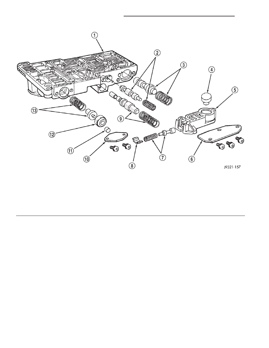
Fig. 262 Upper Housing Shift Valve and Pressure Plug Locations

1 - UPPER HOUSING

8 - RETAINER

2 - 1-2 SHIFT VALVE AND SPRING

9 - 1-2 SHIFT CONTROL VALVE AND SPRING

3 - 2-3 SHIFT VALVE AND SPRING

10 - PRESSURE PLUG COVER

4 - 2-3 THROTTLE PLUG

11 - LINE PRESSURE PLUG

5 - LIMIT VALVE HOUSING

12 - PLUG SLEEVE

6 - LIMIT VALVE COVER

13 - THROTTLE PRESSURE SPRING AND PLUG

7 - LIMIT VALVE AND SPRING

21 - 216

AUTOMATIC TRANSMISSION - 42RE

AN

VALVE BODY (Continued)

Fig. 263 Lower Housing Shift Valves and Springs

1 - 3-4 ACCUMULATOR HOUSING

11 - TIMING VALVE COVER

2 - 3-4 SHIFT VALVE AND SPRING

12 - PLUG

3 - PLUG

13 - 3-4 TIMING VALVE AND SPRING

4 - SPRING RETAINER

14 - LOWER HOUSING

5 - CONVERTER CLUTCH VALVE AND SPRING

15 - ACCUMULATOR END PLATE

6 - CONVERTER CLUTCH TIMING VALVE AND SPRING

16 - 3-4 ACCUMULATOR PISTON AND SPRING

7 - OVERDRIVE SEPARATOR PLATE

17 - E-CLIP

8 - CASE CONNECTOR

18 - 3-4 QUICK FILL SPRING AND VALVE

9 - CONVERTER CLUTCH SOLENOID

19 - SOLENOID GASKET

10 - OVERDRIVE SOLENOID

20 - HARNESS

AN

AUTOMATIC TRANSMISSION - 42RE

21 - 217

VALVE BODY (Continued)

OPERATION

NOTE: Refer to the Hydraulic Schematics for a
visual aid in determining valve location, operation
and design.

CHECK BALLS

CHECK BALL NUMBER

DESCRIPTION

1

Allows either the manual valve to put line pressure on the 1-2 governor plug or
the KD Valve to put WOT line pressure on the 1-2 governor plug.

2

Allows either the manual valve to put line pressure on the 2-3 governor plug or
the KD Valve to put WOT line pressure on the 2-3 governor plug.

3

Allows either the Reverse circuit or the 3rd gear circuit to pressurize the front
clutch.

4

Allows either the Manual Low circuit from the Manual Valve or the Reverse
from the Manual Valve circuit to pressurize the rear servo.

5

Directs line pressure to the spring end of the 2-3 shift valve in either Manual
Low or Manual 2nd, forcing the downshift to 2nd gear regardless of governor
pressure.

6

Provides a by-pass around the front servo orifice so that the servo can release
quickly.

7

Provides a by-pass around the rear clutch orifice so that the clutch can release
quickly.

8

Directs reverse line pressure through an orifice to the throttle valve eliminating
the extra leakage and insuring that Reverse line pressure pressure will be
sufficient.

9

Provides a by-pass around the rear servo orifice so that the servo can release
quickly.

ECE (10)

Allows the lockup clutch to used at WOT in 3rd gear by putting line pressure
from the 3-4 Timing Valve on the interlock area of the 2-3 shift valve, thereby
preventing a 3rd gear Lock-up to 2nd gear kickdown.

21 - 218

AUTOMATIC TRANSMISSION - 42RE

AN

VALVE BODY (Continued)

REGULATOR VALVE

The pressure regulator valve is needed to control

the hydraulic pressure within the system and reduce
the amount of heat produced in the fluid. The pres-
sure regulator valve is located in the valve body near
the manual valve. The pressure regulator valve train
controls the maximum pressure in the lines by
metering the dumping of fluid back into the sump.
Regulated pressure is referred to as “line pressure.”

The regulator valve (Fig. 264) has a spring on one

end that pushes the valve to the left. This closes a
dump (vent) that is used to lower pressure. The clos-
ing of the dump will cause the oil pressure to
increase. Oil pressure on the opposite end of the

valve pushes the valve to the right, opening the
dump and lowering oil pressure. The result is spring
pressure working against oil pressure to maintain
the oil at specific pressures. With the engine run-
ning, fluid flows from the pump to the pressure reg-
ulator valve, manual valve, and the interconnected
circuits. As fluid is sent through passages to the reg-
ulator valve, the pressure pushes the valve to the
right against the large spring. It is also sent to the
reaction areas on the left side of the throttle pressure
plug and the line pressure plug. With the gear selec-
tor in the PARK position, fluid recirculates through
the regulator and manual valves back to the sump.

Fig. 264 Regulator Valve in PARK Position

AN

AUTOMATIC TRANSMISSION - 42RE

21 - 219

VALVE BODY (Continued)


Content   ..  641  642  643  644   ..