Dodge Dakota (R1). Manual - part 641


  Index      Dodge     Dodge Dakota (R1) - service repair manual 2000 year


Search            


Content   ..  639  640  641  642   ..


Dodge Dakota (R1). Manual - part 641


TORQUE CONVERTER
DRAINBACK VALVE

DESCRIPTION

The drainback valve is located in the transmission

cooler outlet (pressure) line.

OPERATION

The valve prevents fluid from draining from the

converter into the cooler and lines when the vehicle
is shut down for lengthy periods. Production valves
have a hose nipple at one end, while the opposite end
is threaded for a flare fitting. All valves have an
arrow (or similar mark) to indicate direction of flow
through the valve.

STANDARD PROCEDURE - TORQUE
CONVERTER DRAINBACK VALVE

The converter drainback check valve is located in

the cooler outlet (pressure) line near the radiator
tank. The valve prevents fluid drainback when the
vehicle is parked for lengthy periods. The valve check
ball is spring loaded and has an opening pressure of
approximately 2 psi.

The valve is serviced as an assembly; it is not

repairable. Do not clean the valve if restricted, or
contaminated by sludge, or debris. If the valve fails,
or if a transmission malfunction occurs that gener-
ates significant amounts of sludge and/or clutch par-
ticles

and

metal

shavings,

the

valve

must

be

replaced.

The valve must be removed whenever the cooler

and lines are reverse flushed. The valve can be flow
tested when necessary. The procedure is exactly the
same as for flow testing a cooler.

If the valve is restricted, installed backwards, or in

the wrong line, it will cause an overheating condition
and possible transmission failure.

CAUTION: The drainback valve is a one-way flow
device. It must be properly oriented in terms of flow
direction for the cooler to function properly. The
valve must be installed in the pressure line. Other-
wise flow will be blocked and would cause an over-
heating condition and eventual transmission failure.
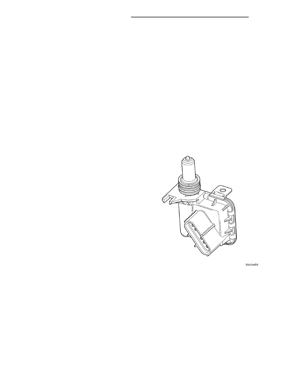
TRANSMISSION RANGE
SENSOR

DESCRIPTION

The Transmission Range Sensor (TRS) (Fig. 251)

has 3 primary functions:

• Provide a PARK/NEUTRAL start signal to the

engine controller and the starter relay.

• Turn the Back-up lamps on when the transmis-

sion is in REVERSE and the engine (ignition) is on.

• Provide a transmission range signal to the

instrument cluster.

Fig. 251 Transmission Range Sensor

21 - 208

AUTOMATIC TRANSMISSION - 42RE

AN

The sensor is mounted in the transmission housing

near the valve body, just above the pan rail. It’s in
the same position as the Park/Neutral switch on
other transmissions. The TRS contacts a cammed
surface on the manual valve lever. The cammed sur-
face translates the rotational motion of the manual
lever into the linear motion of the sensor. The
cammed surface on the manual lever is comprised of
two parts controlling the TRS signal: The insulator
portion contacts the switch poppet when the manual
lever is not in PARK or NEUTRAL. The manual
lever itself contacts the poppet when the lever is in
PARK or NEUTRAL; providing a ground for the sig-
nal from the starter relay and the JTEC engine con-
troller.

OPERATION

As the switch moves through its linear motion (Fig.

252) contacts slide across a circuit board which
changes the resistance between the range sensing
pins of the switch. A power supply on the instrument
cluster provides a regulated voltage signal to the
switch. The return signal is decoded by the cluster,
which then controls the PRNDL display to corre-
spond with the correct transmission range. A bus
message of transmission range is also sent by the
cluster. In REVERSE range a second contact set
closes the circuit providing power to the reverse
lamps.

Fig. 252 Transmission Range Sensor Linear

Movement

AN

AUTOMATIC TRANSMISSION - 42RE

21 - 209

TRANSMISSION RANGE SENSOR (Continued)

Mechanical State

Electronic Display

(Ignition Unlocked)

Electronic Display

(Ignition On)

Indicated Gear Position

Transmission
Status

Column Shifter
Position

P

P

P

Vehicle is in PARK
with the pawl
engaged.

In the PARK gate.

R

The PARK pawl is
disengaged and the
vehicle is free to
roll, but REVERSE
is not engaged.

Between the PARK
and REVERSE
gates.

R

R

R

The transmission is
hydraulically in
REVERSE.

In the REVERSE
gate.

N

The transmission is
transitioning
between REVERSE
and NEUTRAL.

Between the
REVERSE and
NEUTRAL gates.

N

N

N

The vehicle is in
NEUTRAL.

In the NEUTRAL
gate.

N

The transmission is
transitioning
between NEUTRAL
and DRIVE, but is
not in DRIVE.

Between the
NEUTRAL and
DRIVE gates.

D

D

D

The transmission is
hydraulically in
DRIVE.

In the DRIVE gate,

2

2

2

The transmission is
hydraulically in
Manual SECOND.

In the SECOND
gate.

1

1

1

The transmission is
hydraulically in
Manual FIRST.

In the FIRST gate.

DIAGNOSIS AND TESTING - TRANSMISSION
RANGE SENSOR (TRS)

NOTE: For all circuit identification in the following
steps, Refer to the appropriate Wiring Information.

(1) Raise vehicle on suitable hoist.
(2) Disconnect the vehicle’s shift cable from the

manual lever.

(3) With the manual lever in the PARK position

(the PARK position is with the manual lever moved
to the full rearward position), measure the resistance
between the Park/Neutral Position Sense pin of the
TRS and the transmission case. The resistance
should be less than 5 ohms.

(4) With the manual lever in the NEUTRAL position

(the NEUTRAL position is with the manual lever
moved two detents forward of the full rearward posi-
tion), measure the resistance between the Park/Neutral
Position Sense pin of the TRS and the transmission
case. The resistance should be less than 5 ohms.

(5) If the resistance is greater than 5 ohms in

either of the previous steps, check for a dirty contact
between the tip of the TRS rod and the valve body
manual lever. If the contact is OK, replace the TRS.

(6) With the manual lever in the REVERSE position

(the REVERSE position is with the manual lever
moved one detent forward of the full rearward posi-
tion), measure the resistance between the Fused Igni-
tion Switch Output and the Back-up Lamp feed pins of
the TRS. The resistance should be less than 5 ohms. If
the resistance is greater than 5 ohms, replace the TRS.

21 - 210

AUTOMATIC TRANSMISSION - 42RE

AN

TRANSMISSION RANGE SENSOR (Continued)

(7) With the manual lever in the PARK position

(the PARK position is with the manual lever moved
to the full rearward position), measure the resistance
between the Cluster Resistance Signal and the Clus-
ter Signal Return pins of the TRS. The resistance
should be 522.2 ohms. If the resistance is not correct,
replace the TRS.

(8) With the manual lever in the REVERSE posi-

tion (the REVERSE position is with the manual lever
moved one detent forward of the full rearward posi-
tion), measure the resistance between the Cluster
Resistance Signal and the Cluster Signal Return pins
of the TRS. The resistance should be 206.2 ohms. If
the resistance is not correct, replace the TRS.

(9) With the manual lever in the NEUTRAL posi-

tion (the NEUTRAL position is with the manual
lever moved two detents forward of the full rearward
position), measure the resistance between the Cluster
Resistance Signal and the Cluster Signal Return pins
of the TRS. The resistance should be 108.6 ohms. If
the resistance is not correct, replace the TRS.

(10) With the manual lever in the DRIVE position

(the DRIVE position is with the manual lever moved
three detents forward of the full rearward position),
measure the resistance between the Cluster Resis-
tance Signal and the Cluster Signal Return pins of
the TRS. The resistance should be 59.9 ohms. If the
resistance is not correct, replace the TRS.

(11) With the manual lever in the SECOND posi-

tion (the SECOND position is with the manual lever
moved one detent rearward of the full forward posi-
tion), measure the resistance between the Fused
Ignition Switch Output and the Back-up Lamp feed
pins of the TRS. The resistance should be 31.9 ohms.
If the resistance is not correct, replace the TRS.

(12) With the manual lever in the LOW position

(the LOW position is with the manual lever moved to
the full forward position), measure the resistance
between the Fused Ignition Switch Output and the
Back-up Lamp feed pins of the TRS. The resistance
should be 13.7 ohms. If the resistance is not correct,
replace the TRS.

REMOVAL

(1) Raise vehicle and position drain pan under the

transmission range sensor (TRS).

(2) Move the transmission manual lever to the

manual LOW position. The manual LOW position is
with the manual lever in the forward-most detent.

(3) Disengage the wiring connector from the TRS.
(4) Remove the two screws holding the TRS to the

TRS mounting bracket.

(5) Remove the TRS (Fig. 253) from the TRS

mounting bracket by pulling it straight out of the
bracket.

(6) Loosen the TRS mounting bracket in the trans-

mission case using Adapter 8581 (Fig. 254).

Fig. 253 Remove Transmission Range Sensor

1 - SOLENOID CASE CONNECTOR
2 - TRS MOUNTING BRACKET
3 - TRANSMISSION RANGE SENSOR

Fig. 254 Loosen the TRS Mounting Bracket

1 - SOLENOID CASE CONNECTOR
2 - TRS MOUNTING BRACKET
3 - ADAPTER 8581

AN

AUTOMATIC TRANSMISSION - 42RE

21 - 211

TRANSMISSION RANGE SENSOR (Continued)


Content   ..  639  640  641  642   ..