Dodge Dakota (R1). Manual - part 642


  Index      Dodge     Dodge Dakota (R1) - service repair manual 2000 year


Search            


Content   ..  640  641  642  643   ..


Dodge Dakota (R1). Manual - part 642


(7) Remove the TRS mounting bracket (Fig. 255)

from the transmission case.

INSTALLATION

(1) Move the transmission manual shaft lever to

the manual LOW position.

(2) Install the TRS mounting bracket into the

transmission case. Using Adapter 8581 (Fig. 256),
tighten the mounting bracket to 34 N·m (300 in.lbs.).

(3) Install the TRS (Fig. 257) into the mounting

bracket with the wiring connector facing the front of
the transmission.

(4) Install the two screws to hold the TRS to the

mounting bracket. Tighten the screws to 3.4 N·m (30
in.lbs.).

(5) Verify proper sensor operation (Fig. 258).

(6) Move the transmission manual shaft lever to

the PARK position.

(7) Connect TRS wiring connector to the TRS and

lower vehicle.

(8) Refill the transmission fluid to the correct

level.

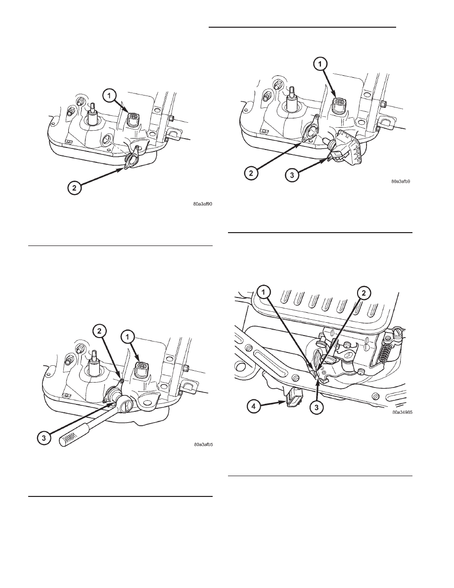
Fig. 255 Remove TRS Mounting Bracket

1 - SOLENOID CASE CONNECTOR
2 - TRS MOUNTING BRACKET

Fig. 256 Tighten the TRS Mounting Bracket

1 - SOLENOID CASE CONNECTOR
2 - TRS MOUNTING BRACKET
3 - ADAPTER 8581

Fig. 257 Remove Transmission Range Sensor

1 - SOLENOID CASE CONNECTOR
2 - TRS MOUNTING BRACKET
3 - TRANSMISSION RANGE SENSOR

Fig. 258 Transmission Range Sensor Operation

1 - NEUTRAL CONTACT
2 - MANUAL LEVER AND SENSOR PLUNGER IN REVERSE
POSITION
3 - PARK CONTACT
4 - TRANSMISSION RANGE SENSOR

21 - 212

AUTOMATIC TRANSMISSION - 42RE

AN

TRANSMISSION RANGE SENSOR (Continued)

TRANSMISSION
TEMPERATURE SENSOR

DESCRIPTION

Transmission fluid temperature readings are sup-

plied to the transmission control module by the ther-
mistor (Fig. 259). The temperature readings are used
to control engagement of the fourth gear overdrive
clutch, the converter clutch, and governor pressure.
Normal resistance value for the thermistor at room
temperature is approximately 1000 ohms.

The thermistor is part of the governor pressure

sensor assembly and is immersed in transmission
fluid at all times.

OPERATION

The PCM prevents engagement of the converter

clutch and overdrive clutch, when fluid temperature
is below approximately 10°C (50°F).

If fluid temperature exceeds 126°C (260°F), the

PCM causes a 4-3 downshift and engage the con-
verter clutch. Engagement is according to the third
gear converter clutch engagement schedule.

The overdrive OFF lamp in the instrument panel

illuminates when the shift back to third occurs. The
transmission will not allow fourth gear operation
until fluid temperature decreases to approximately
110°C (230°F).

VALVE BODY

DESCRIPTION

The valve body consists of a cast aluminum valve

body, a separator plate, and transfer plate. The valve
body contains valves and check balls that control
fluid delivery to the torque converter clutch, bands,
and frictional clutches. The valve body contains the
following components (Fig. 260), (Fig. 261), (Fig.
262), and (Fig. 263):

• Regulator valve

• Regulator valve throttle pressure plug

• Line pressure plug and sleeve

• Kickdown valve

• Kickdown limit valve

• 1-2 shift valve

• 1-2 control valve

• 2-3 shift valve

• 2-3 governor plug

• 3-4 shift valve

• 3-4 timing valve

• 3-4 quick fill valve

• 3-4 accumulator

• Throttle valve

• Throttle pressure plug

• Switch valve

• Manual valve

• Converter clutch lock-up valve

• Converter clutch lock-up timing Valve

• Shuttle valve

• Shuttle valve throttle plug

• Boost Valve

• 10 check balls
By adjusting the spring pressure acting on the reg-

ulator valve, transmission line pressure can be
adjusted.

Fig. 259 Governor Pressure Sensor

1 - GOVERNOR BODY
2 - GOVERNOR PRESSURE SENSOR/TRANSMISSION FLUID
TEMPERATURE THERMISTOR

AN

AUTOMATIC TRANSMISSION - 42RE

21 - 213

Fig. 260 Upper Housing Control Valve Locations

1 - UPPER HOUSING

8 - MANUAL VALVE

2 - REGULATOR VALVE

9 - 1-2 GOVERNOR PLUG

3 - SWITCH VALVE

10 - GOVERNOR PLUG COVER

4 - REGULATOR VALVE SPRING

11 - THROTTLE PLUG

5 - KICKDOWN VALVE

12 - 2-3 GOVERNOR PLUG

6 - KICKDOWN DETENT

13 - SHUTTLE VALVE PRIMARY SPRING

7 - THROTTLE VALVE AND SPRING

21 - 214

AUTOMATIC TRANSMISSION - 42RE

AN

VALVE BODY (Continued)

Fig. 261 Shuttle and Boost Valve Locations

1 - SPRING

8 - SHUTTLE VALVE COVER

2 - RETAINER

9 - SHUTTLE VALVE

3 - BOOST VALVE

10 - SHUTTLE VALVE PRIMARY SPRING

4 - BOOST VALVE PLUG

11 - GOVERNOR PLUG COVER

5 - SPRING GUIDES

12 - THROTTLE PLUG

6 - E-CLIP

13 - UPPER HOUSING

7 - SHUTTLE VALVE SECONDARY SPRING

14 - BOOST VALVE COVER

AN

AUTOMATIC TRANSMISSION - 42RE

21 - 215

VALVE BODY (Continued)


Content   ..  640  641  642  643   ..