Dodge Dakota (R1). Manual - part 604
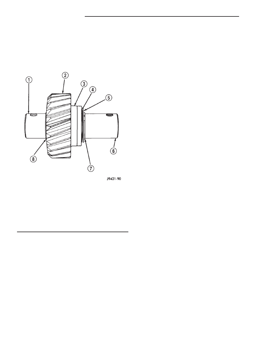
(7) Install lock ball in dimple at front of shaft.
Hold ball in place with petroleum jelly.
(8) Install front thrust washer on shaft and slide
washer up against gear and over lock ball (Fig. 83).
(9) Install wave washer, flat washer and remain-
ing snap ring on idler shaft (Fig. 83). Verify snap
ring is seated.
SHIFT SHAFT AND BUSHINGS/BEARINGS
Inspect shift shaft bushing and bearing for damage
and replace if necessary.
(1) Locate a bolt that will thread into the bushing
without great effort.
(2) Thread the bolt into the bushing, allowing the
bolt to make its own threads in the bushing.
(3) Attach a slide hammer or suitable puller to the
bolt and remove bushing.
(4) Use the short end of Installer 8119 to install
the new bushing.
(5) The bushing is correctly installed if the bush-
ing is flush with the transmission case.
(6) To replace the bearing locate a bolt that will
thread into the bearing without great effort.
(7) Thread the bolt into the bearing as much as
possible.
(8) Attach a slide hammer or suitable puller to the
bolt and remove the bearing.
(9) Use the short end of Installer 8119 to install
the new bearing.
(10) The bearing is correctly installed if the bear-
ing is flush with the transmission case.
DETENT PLUNGER BUSHING
Inspect detent plunger bushings for damage and
replace if necessary.
NOTE: The detent plunger bushings are installed to
a specific depth. The space between the two bush-
ings when correctly installed contain an oil feed
hole. Do not attempt to install the bushings with
anything other than the specified tool or this oil
hole may become restricted.
(1) Using the long end of Installer 8119, drive the
detent bushings through the outer case and into the
shift shaft bore.
(2) Remove the bushings from the shift shaft bore.
(3) Install a new detent plunger bushing on the
long end of Installer 8118.
(4) Start the bushing in the detent plunger bore in
the case.
(5) Drive the bushing into the bore until the tool
contacts the transmission case.
(6) Install a new detent plunger bushing on the
short end of Installer 8118.
(7) Start the bushing in the detent plunger bore in
the case.
(8) Drive the bushing into the bore until the tool
contacts the transmission case.
GEARTRAIN ASSEMBLY
(1) Install Adapter 6747-1A on input shaft hub of
Fixture 6747 (Fig. 84).
(2) Install input shaft in fixture tool. Make sure
Adapter 6747-1A is positioned under shaft as shown
(Fig. 85).
(3) Install pilot bearing in input shaft (Fig. 85).
NOTE: The side of the pilot bearing with the small
diameter goes toward the input shaft.
Fig. 83 IDLER GEAR AND SHAFT ASSEMBLY
1 - REAR OF SHAFT
2 - GEAR
3 - THRUST WASHER AND BALL
4 - WAVE WASHER
5 - FLAT WASHER
6 - FRONT OF SHAFT
7 - SNAP RING
8 - SNAP RING
21 - 60
MANUAL - NV3500
AN
MANUAL - NV3500 (Continued)