Dodge Dakota (R1). Manual - part 603


  Index      Dodge     Dodge Dakota (R1) - service repair manual 2000 year


Search            


Content   ..  601  602  603  604   ..


Dodge Dakota (R1). Manual - part 603


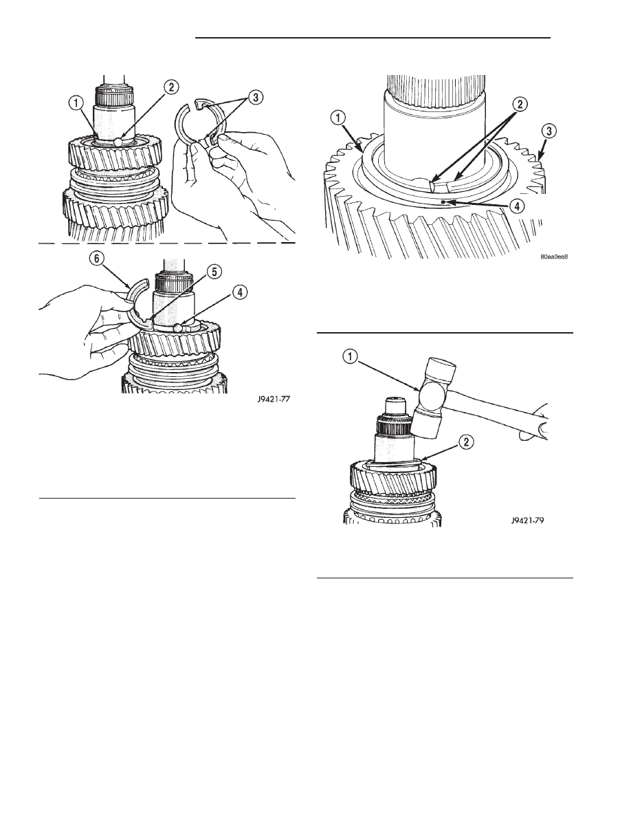
(24) Start retaining ring around two-piece thrust

washer (Fig. 71). Ensure locating dimple is between
the thrust washer halves.

(25) Seat thrust washer retaining ring with plastic

mallet (Fig. 72).

(26) Install third gear needle bearing on shaft (Fig.

73).

Fig. 70 TWO-PIECE THRUST WASH

1 - WASHER GROOVE IN SHAFT
2 - LUG BORE
3 - THRUST WASHER LUGS
4 - LUG BORE
5 - LUG
6 - WASHER HALF

Fig. 71 RETAINING RING

1 - THRUST WASHER RETAINING RING
2 - THRUST WASHER HALVES
3 - SECOND GEAR
4 - LOCATING DIMPLE

Fig. 72 THRUST WASHER

1 - PLASTIC MALLET
2 - THRUST WASHER RETAINING RING

21 - 56

MANUAL - NV3500

AN

MANUAL - NV3500 (Continued)

(27) Install third gear on shaft and bearing (Fig.

74).

(28) Install third speed synchro ring on third gear

(Fig. 75).

(29) Assemble 3-4 synchro hub, sleeve, springs,

struts and detent balls.

(30) Start 3-4 synchro hub on output shaft splines

by hand (Fig. 76).

CAUTION: The 3-4 synchro hub and sleeve can be
installed backwards. One side of the sleeve has
grooves in it. This side of sleeve faces the front of
the shaft.

Fig. 73 THIRD GEAR BEARING

1 - THIRD GEAR BEARING

Fig. 74 THIRD GEAR

1 - THIRD GEAR
2 - BEARING

Fig. 75 THIRD SPEED SYNCHRO RING

1 - THIRD SPEED SYNCHRO RING
2 - THIRD GEAR

Fig. 76 3-4 SYNCHRO HUB ON OUTPUT SHAFT

1 - GROOVED SIDE OF SLEEVE (TO FRONT)
2 - 3-4 SYNCHRO ASSEMBLY

AN

MANUAL - NV3500

21 - 57

MANUAL - NV3500 (Continued)

(31) Press 3-4 synchro assembly onto output shaft

with shop press and suitable size pipe tool (Fig. 77).

NOTE: Place the pipe on hub as close to output
shaft as possible without contacting the shaft
splines.

(32) Install 3-4 synchro hub snap ring (Fig. 78)and

verify snap ring is seated.

NOTE: Snap rings are available in thicknesses from
2.00 mm to 2.30 mm (0.078 to 0.090 in.). Install
thickest snap ring that will fit in shaft groove.

(33) Install output shaft bearing.
(34) Install output shaft bearing snap ring, spread-

ing it just enough to install it (Fig. 79). Verify snap
ring is seated in shaft groove.

(35) Verify position of synchro sleeves before pro-

ceeding with assembly operations (Fig. 80). Grooved
side of 3-4 sleeve should be facing forward. First gear
side of 1-2 sleeve should be facing first gear. Tapered
side of fifth-reverse sleeve should be facing forward.

REVERSE IDLER ASSEMBLY

(1) Lubricate idler components with gear lube.
(2) Slide idler gear bearing on shaft (Fig. 81).

Bearing fits either way on shaft.

(3) Slide gear onto shaft. Side of gear with recess

goes to rear (Fig. 81).

(4) Place first lock ball in dimple at rear end of

idler shaft (Fig. 81). Hold ball in place with petro-
leum jelly.

(5) Slide thrust rear thrust washer onto shaft and

over lock ball (Fig. 82).

(6) Install snap ring in groove at rear of shaft (Fig.

82).

Fig. 77 PRESS 3-4 SYNCHRO ON OUTPUT SHAF

1 - PRESS RAM
2 - PIPE TOOL
3 - 3-4 SYNCHRO
4 - THIRD SPEED SYNCHRO RING

Fig. 78 3-4 SYNCHRO HUB SNAP RING

1 - 3-4 SYNCHRO HUB SNAP RING
2 - SNAP RING PLIERS

Fig. 79 OUTPUT SHAFT BEARING

1 - BEARING SNAP RING
2 - SNAP RING PLIERS

21 - 58

MANUAL - NV3500

AN

MANUAL - NV3500 (Continued)

Fig. 80 SYNCHRO SLEEVE LOCATIONS

1 - DOUBLE GROOVE FORWARD
2 - GROOVE FORWARD
3 - FIRST GEAR SIDE MARKING TOWARD FIRST GEAR
4 - TAPER FORWARD

5 - GROOVE FORWARD
6 - 5TH-REV SYNCHRO SLEEVE
7 - 1-2 SYNCHRO SLEEVE
8 - 3-4 SYNCHRO SLEEVE

Fig. 81 IDLER GEAR AND BEARING

1 - IDLER GEAR
2 - BEARING
3 - LOCK BALL
4 - REAR OF SHAFT

Fig. 82 IDLER GEAR REAR THRUST WASHER

1 - LOCK BALL
2 - SNAP RING GROOVE
3 - THRUST WASHER

AN

MANUAL - NV3500

21 - 59

MANUAL - NV3500 (Continued)


Content   ..  601  602  603  604   ..