Dodge Dakota (R1). Manual - part 558
SPECIAL TOOLS
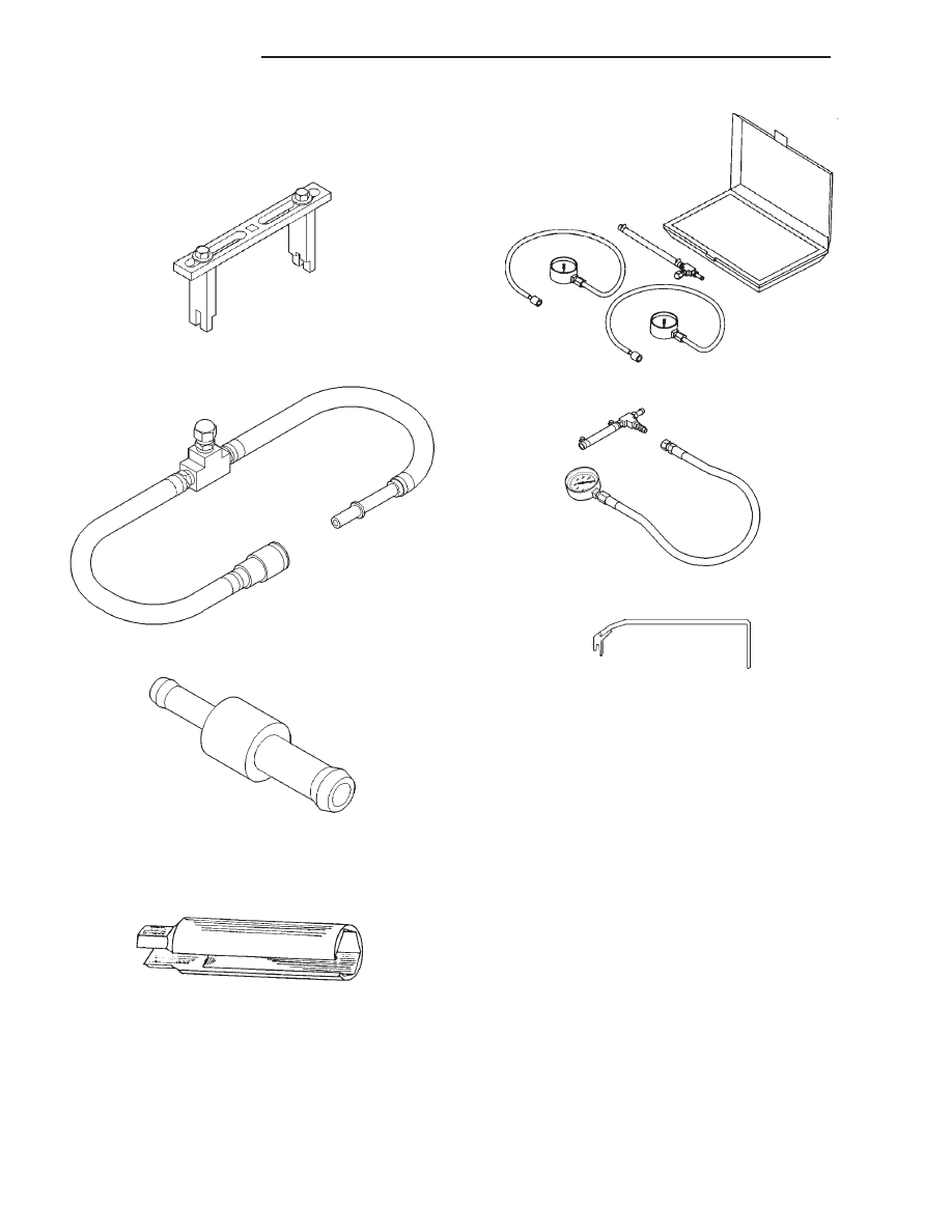
FUEL SYSTEM
Spanner Wrench—6856
Adapters, Fuel Pressure Test—6539 and/or 6631
Fitting, Air Metering—6714
O2S (Oxygen Sensor) Remover/Installer—C-4907
Test Kit, Fuel
Test Kit, Fuel Pressure—C-4799-B
Fuel Line Removal Tool—6782
14 - 4
FUEL DELIVERY
AN
FUEL DELIVERY (Continued)