Dodge Dakota (R1). Manual - part 556


  Index      Dodge     Dodge Dakota (R1) - service repair manual 2000 year


Search            


Content   ..  554  555  556  557   ..


Dodge Dakota (R1). Manual - part 556


FRAME REPAIRS

If a R-1 frame requires any repair such as straight-

ening, welding or drilling please refer to the AN ser-
vice manual, Frame section for detailed instructions.
Refer to the specifications section of this group for
R-1 frame specifications.

SPECIFICATIONS

VEHICLE DIMENSIONS

For R1 body dimensions refer to the AN service

manual – Body – section for a complete list of all
body specifications.
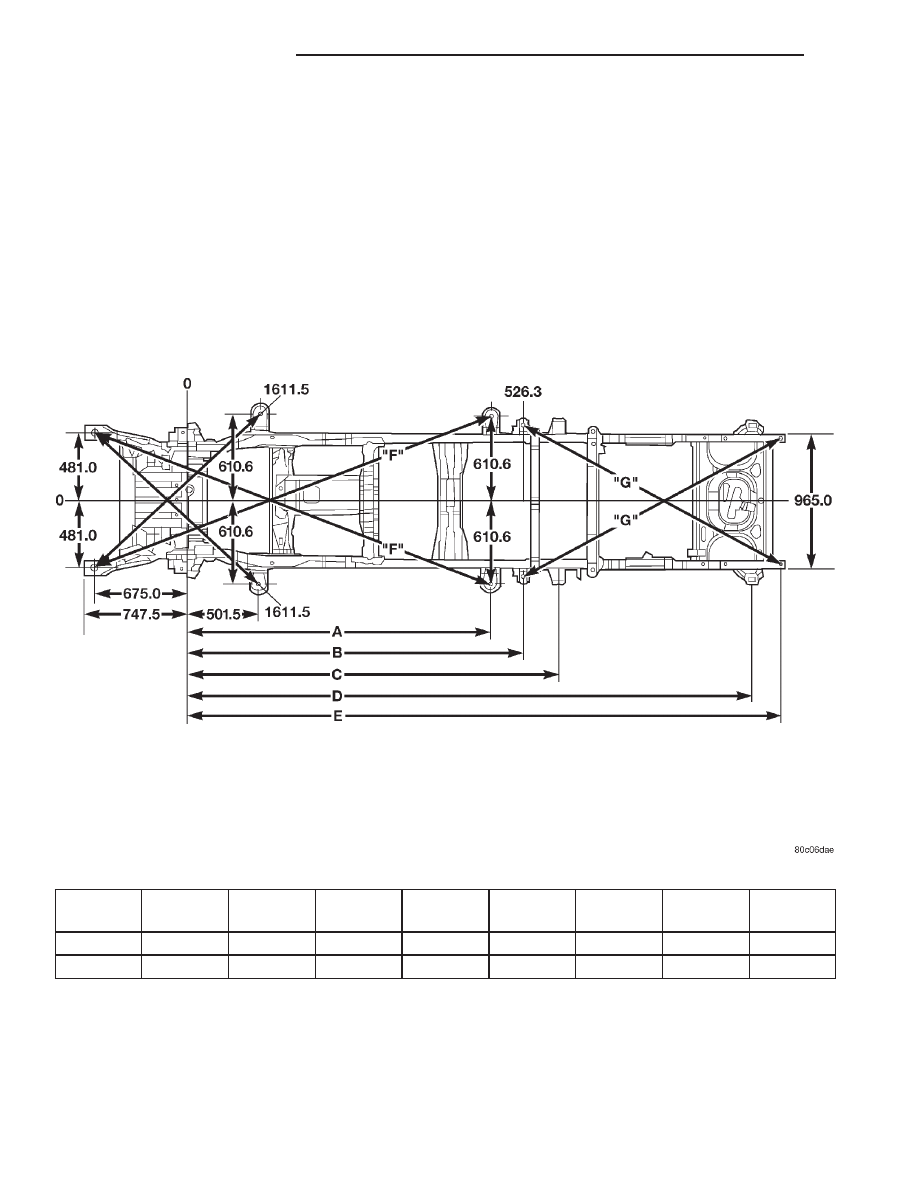
FRAME TOP VIEW

4x2 – Automatic Transmission

WHEEL

BASE

4X2
4X4

DIMN
A

DIMN
B

DIMN
C

DIMN
D

DIMN
E

DIMN
F

DIMN
G

112

4X4

1674.8

1901.0

2159.3

3539.4

3738.5

2591.0

2081.7

131

4X4

2156.7

2383.0

2641.9

4022.0

4220.5

3034.9

2081.7

13a - 2

FRAME & BUMPERS

R1

FRAME-R1 (Continued)

4x2 – Manual Transmission

WHEEL
BASE

4X2
4X4

DIMN
A

DIMN

B

DIMN
C

DIMN
D

DIMN
E

DIMN
F

DIMN
G

112

4X4

1674.8

1901.0

2159.3

3539.4

3738.5

2591.0

2081.7

131

4X4

2156.7

2383.0

2641.9

4022.0

4220.5

3034.9

2081.7

R1

FRAME & BUMPERS

13a - 3

FRAME-R1 (Continued)

FRAME SIDE VIEW

SPECIFICATIONS - TORQUE

DESCRIPTION

TORQUE

Front skid plate-to-front

x-member bolt

41 N·m (30 ft. lbs.)

Fuel tank skid plate to

x-member bolts

41 N·m (30 ft. lbs.)

Rear bumper-to-brace

nut

94 N·m (70 ft. lbs.)

Rear bumper brace-to-

brkt nut

94 N·m (70 ft. lbs.)

Rear bumper brkt-to-

frame nut

94 N·m (70 ft. lbs.)

Trailer hitch nut

108 N·m (80 ft. lbs.)

Diesel x-member to

frame

65 N·m (48 ft. lbs.)

Transmission mount to

transmission

47 N·m (35 ft. lbs.)

Exhaust system support

bracket to x-member

67 N·m (50 ft. lbs.)

FRONT AXLE SKID PLATE-R1

REMOVAL

(1) Raise and support the vehicle.
(2) Position a jack stand under the skid plate.

WARNING: SKID PLATE IS SHARP. WEAR GLOVES
TO PREVENT INJURY.

(3) Remove the eight (8) bolts and nuts that attach

the skid plate to the frame.

(4) Remove the skid plate from the vehicle.

INSTALLATION

WARNING: SKID PLATE IS SHARP. WEAR GLOVES
TO PREVENT INJURY.

(1) Position the skid plate on the jack stand under

the vehicle.

(2) Lift the skid plate in position and install the

eight (8) bolts and nuts that attach the skid plate to
the frame. Torque to 41 N·m (30 ft. lbs.).

(3) Remove the jack stand from under the vehicle.
(4) Lower the vehicle.

FUEL TANK SKID PLATE R-1

REMOVAL

(1) Raise and support the vehicle.
(2) Position a jack stand under the skid plate.

WARNING: SKID PLATE IS SHARP. WEAR GLOVES
TO PREVENT INJURY.

(3) Remove the fasteners that attach the skid plate

to the support bracket and the frame side rail
(Fig. 1).

(4) Remove the support bracket and skid plate

from the vehicle.

INSTALLATION

(1) Position skid plate and support on the jack

stand under its mounting position.

(2) Lift the skid plate into position and install

retaining fasteners. Torque to 41 N·m (30 ft. lbs.).

(3) Remove the jack stand from under the vehicle.
(4) Lower the vehicle.

Frame Side View

13a - 4

FRAME & BUMPERS

R1

FRAME-R1 (Continued)

MANUAL TRANSMISSION
CROSSMEMBER-R-1

REMOVAL - MANUAL TRANSMISSION
CROSSMEMBER – 2.5L DIESEL

(1) Disconnect and isolate the negative battery

cable.

(2) Remove the upper fan shroud retaining bolts.
(3) Raise and support the vehicle.
(4) Remove the lower fan shroud retaining bolts.
(5) Support the transmission with a jack stand.
(6) Remove the four transmission mount bolts

(Fig. 2) and slightly raise the transmission.

(7) Remove the exhaust system support bracket

retaining nut (Fig. 2).

(8) Remove the fuel line support bracket retaining

bolt from the left side of the transmission crossmem-
ber.

(9) Remove the eight crossmember retaining bolts

from the frame rails.

(10) Significant force will be required to remove

the crossmember from the frame rails. Remove the
crossmember from between the frame rails.

INSTALLATION - MANUAL TRANSMISSION
CROSSMEMBER – 2.5L DIESEL

(1) Install the crossmember between the frame

rails.

(2) Install the eight crossmember retaining bolts.

Torque to 65 N·m (48 ft. lbs.).

(3) Lower the transmission and install the trans-

mission mount retaining bolts (Fig. 2). Torque to
47 N·m (35 ft. lbs.).

(4) Install the exhaust system support bracket

retaining nut (Fig. 2).

(5) Install the fuel line support bracket retaining

bolt from the left side of the transmission crossmem-
ber.

(6) Remove the jack stand from the transmission.
(7) Install the fuel line clip to the crossmember.
(8) Install the lower fan shroud retaining bolts.
(9) Lower the vehicle.
(10) Install the upper fan shroud retaining bolts.
(11) Connect the negative battery cable.

Fig. 1 Fuel Tank Skid Plate Position & Orientation

1 - SKID PLATE SUPPORT BRACKET
2 - SCREW
3 - FUEL TANK
4 - FUEL TANK CROSSMEMBER
5 - FRAME CROSSMEMBER
6 - LOCK NUT
7 - SCREW
8 - SKID PLATE
9 - U-NUT
10 - FRAME RAIL

Fig. 2 Transmission Support Crossmember

1 - EXHAUST SYSTEM SUPPORT BRACKET RETAINING NUT
2 - CROSSMEMBER
3 - TRANSMISSION
4 - TRANSMISSION MOUNT RETAINING NUTS

R1

FRAME & BUMPERS

13a - 5

FUEL TANK SKID PLATE R-1 (Continued)


Content   ..  554  555  556  557   ..