Dodge Dakota (R1). Manual - part 546
INSTALLATION
CAUTION: If the studs came out with the nuts when
removing the exhaust manifold, install new studs.
(1) Position the exhaust manifolds on the two
studs located on the cylinder head. Install conical
washers and nuts on these studs (Fig. 70).
(2) Install new bolt and washer assemblies in the
remaining holes (Fig. 70). Start at the center arm
and work outward. Tighten the bolts and nuts to 24
N·m (18 ft. lbs.) torque.
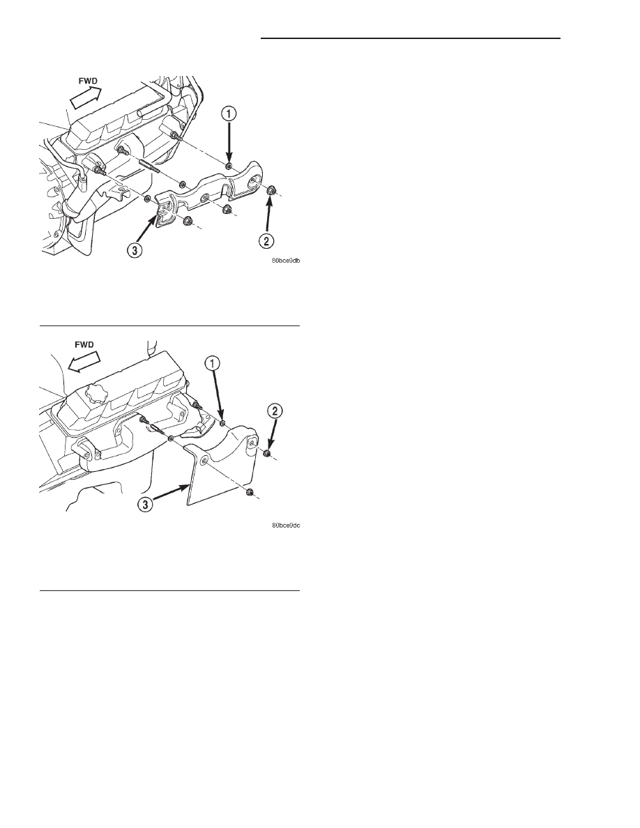
(3) Position three washers, heat shield and nuts on
the right side exhaust manifold. Tighten nuts to 24
N·m (18 ft. lbs.).
(4) Position two washers, heat shield and nuts on
the left side exhaust manifold. Tighten nuts to 24
N·m (18 ft. lbs.).
(5) Raise and support the vehicle.
(6) Assemble the exhaust pipe to the exhaust man-
ifold and secure with bolts, nuts and washers.
Tighten these nuts to 27 N·m (20 ft. lbs.) torque.
(7) Lower the vehicle.
(8) Connect the negative cable to the battery.
VALVE TIMING
STANDARD PROCEDURE - VALVE TIMING
(1) Turn crankshaft until the No.6 exhaust valve is
closing and No.6 intake valve is opening.
(2) Insert a 6.350 mm (1/4 inch) spacer between
rocker arm pad and stem tip of No.1 intake valve.
Allow spring load to bleed tappet down giving in
effect a solid tappet.
(3) Install a dial indicator so plunger contacts
valve spring retainer as nearly perpendicular as pos-
sible. Zero the indicator.
(4) Rotate the crankshaft clockwise (normal run-
ning direction) until the valve has lifted 0.863 mm
(0.034 inch). The timing of the crankshaft should
now read from 10° before top dead center to 2° after
top dead center. Remove spacer.
CAUTION: DO NOT turn crankshaft any further
clockwise as valve spring might bottom and result
in serious damage.
If reading is not within specified limits:
• Check sprocket index marks.
• Inspect timing chain for wear.
• Check accuracy of DC mark on timing indicator.
TIMING BELT / CHAIN
COVER(S)
REMOVAL
(1) Disconnect the negative cable from the battery.
(2) Drain cooling system (Refer to 7 - COOLING/
ENGINE - STANDARD PROCEDURE).
(3) Remove the serpentine belt (Refer to 7 - COOL-
ING/ACCESSORY DRIVE/DRIVE BELTS - REMOV-
AL).
(4) Remove water pump (Refer to 7 - COOLING/
ENGINE/WATER PUMP - REMOVAL).
(5) Remove power steering pump (Refer to 19 -
STEERING/PUMP - REMOVAL).
Fig. 71 Exhaust Manifold Heat Shield - Right Side
1 - WASHER
2 - NUT AND WASHER
3 - EXHAUST MANIFOLD HEAT SHIELD
Fig. 72 Exhaust Manifold Heat Shield - Left Side
1 - WASHER
2 - NUT AND WASHER
3 - EXHAUST MANIFOLD HEAT SHIELD
9a - 102
ENGINE 5.2L INTERNATIONAL
R1
EXHAUST MANIFOLD (Continued)