Dodge Dakota (R1). Manual - part 528


  Index      Dodge     Dodge Dakota (R1) - service repair manual 2000 year


Search            


Content   ..  526  527  528  529   ..


Dodge Dakota (R1). Manual - part 528


CYLINDER HEAD

DESCRIPTION - CLYINDER HEAD GASKETS

A steel cylinder head gasket is used for all four cyl-

inder heads.

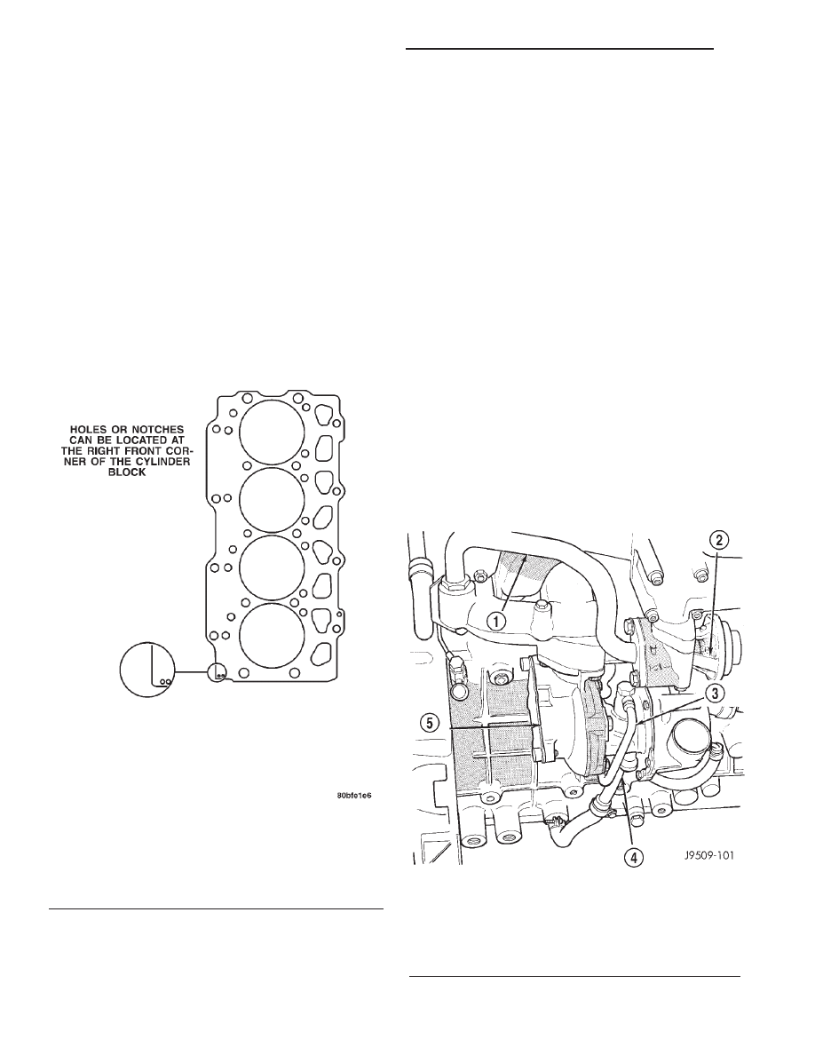
Cylinder head gaskets are available in three thick-

nesses. Identification holes in the right front corner
of the gasket indicate the thickness of the gasket
(Fig. 26).

CAUTION: Piston protrusion must be measured, to
determine cylinder head gasket thickness, if one or
more cylinder wall liners have been replaced.

NOTE:

If

cylinder

wall

liners

have

not

been

removed; the same thickness head gasket removed,
may be used.

REMOVAL

(1) Disconnect the negative battery cable.

WARNING:

DO

NOT

REMOVE

THE

CYLINDER

BLOCK DRAIN PLUGS OR LOOSEN THE RADIATOR
DRAIN COCK WITH THE SYSTEM HOT AND PRES-
SURIZED BECAUSE SERIOUS BURNS FROM THE
COOLANT CAN OCCUR.

(2) Drain the cooling system (Refer to 7 - COOL-

ING/ENGINE - STANDARD PROCEDURE).

(3) Discharge

the

air

conditioning

system,

if

equipped. (Refer to 24 - HEATING & AIR CONDI-
TIONING/PLUMBING/REFRIGERANT

-

STAN-

DARD PROCEDURE).

(4) If equipped with air conditioning, remove the

A/C lines at the compressor and cap. Refer to Group
24, Heating and Air Conditioning. Remove A/C line
bracket attached to cylinder head cover, and move
A/C lines away from cylinder head.

(5) Remove the air cleaner hose from turbocharger

and breather hose.

(6) Remove the air cleaner assembly and breather

hose.

(7) Remove the generator support bracket.
(8) Remove the upper radiator hose and coolant

recovery hose.

(9) Remove the water manifold and recovery hose.
(10) Disconnect

the

heater

hoses

and

coolant

recover bottle hose.

Fig. 26 Steel Type Cylinder Head Gasket—

identification

HOW TO IDENTIFY GASKET THICKNESS

NO HOLES

1.41 mm

2 HOLES

1.51 mm

1 HOLE

1.61 mm

Fig. 27 Turbocharger

1 - EGR TUBE
2 - EGR VALVE
3 - OIL FEED LINE
4 - OIL DRAIN
5 - TURBO

9a - 30

ENGINE 2.5L VM DIESEL INTERNATIONAL

R1

(11) Disconnect the EGR tube from EGR valve.
(12) Remove the EGR valve.
(13) Remove the exhaust heat shield from exhaust

manifold.

(14) Remove the exhaust heat shield from down

pipe.

(15) Remove the exhaust down pipe from turbo-

charger (Fig. 27).

(16) Disconnect the oil feed line from turbocharger.
(17) Disconnect the oil drain line from turbo-

charger.

(18) Remove the Exhaust manifold (Refer to 11 -

EXHAUST

SYSTEM/TURBOCHARGER

SYSTEM/

TURBOCHARGER - REMOVAL).

(19) Remove the Intake manifold. Refer to intake

manifold removal and installation for procedure.

(20) Remove the oil feed line retaining bracket at

rear of #4 cylinder head.

(21) Remove the oil feed line retaining bracket

(Fig. 28).

(22) Remove the oil feed line for rocker arm

assemblies (Fig. 29).

(23) Remove the Crankcase breather hose from

rear of the valve cover.

(24) Remove the injector sensor wire and the glow

plug hot lead.

(25) Remove the fuel lines and fuel filter. Refer to

Group 14, Fuel Systems for procedure.

(26) Remove the injector fuel lines from injectors

to pump.

(27) Remove the fuel injectors with tool VM.1012

(Fig. 30). (Refer to 14 - FUEL SYSTEM/FUEL
DELIVERY/FUEL INJECTOR - REMOVAL).

(28) Remove the engine cylinder head cover.
(29) Remove the rocker retaining nuts (Fig. 31).
(30) Remove the rocker arm assemblies. Place

them on a bench in the same order as removed.

(31) Remove the push rods and place them on a

bench in the same order as removed.

(32) Mark the cylinder head positions.
(33) Remove the engine cylinder head bolts with

special tool VM.1018 and VM.1019.

(34) Remove the engine cylinder head and gasket.
(35) Stuff clean lint free shop towels into the cyl-

inder bores.

Fig. 28 Oil Feed Line Retainer

1 - CYLINDER HEAD OIL SUPPLY LINE RETAINING CLIP
2 - EXHAUST MANIFOLD
3 - CYLINDER HEAD OIL SUPPLY LINE
4 - REAR OF CYLINDER HEADS
5 - CYLINDER HEAD COVER

Fig. 29 Rocker Arm Oil Feed Lines

Fig. 30 Fuel Injector Tool VM.1012B

R1

ENGINE 2.5L VM DIESEL INTERNATIONAL

9a - 31

CYLINDER HEAD (Continued)

CLEANING

Thoroughly clean the engine cylinder head and cyl-

inder block mating surfaces. Clean the intake and
exhaust manifold and engine cylinder head mating
surfaces. Remove all gasket material and carbon.

Check to ensure that no coolant or foreign material

has fallen into the tappet bore area.

Remove the carbon deposits from the combustion

chambers and top of the pistons.

INSPECTION

Use a straightedge and feeler gauge to check the

flatness of the engine cylinder head and block mating
surfaces (Fig. 32).

Minimum cylinder head thickness 89.95mm (3.541

in.)

CAUTION: If only one cylinder head is found to be
distorted and requires machining, it will also be
necessary

to

machine

the

remaining

cylinders

heads and end plates by a corresponding amount
to maintain correct cylinder alignment.

INSTALLATION

(1) Remove the shop towels from the cylinder

bores. Coat the bores with clean engine oil.

(2) Install cylinder head alignment studs VM.1009.

(3) After determining the correct head gasket

thickness, clean the block and head mating surfaces,
place the engine cylinder head gasket over the align-
ment studs.

(4) Place the engine cylinder head over the align-

ment studs.

CAUTION: New cylinder head bolts should be used.

(5) Tighten the engine cylinder head bolts in

sequence according to the following procedure (Fig.
33):

(a) The threads and underside heads of the bolts

should be lubricated. Use the cylinder head align-
ment studs tool number VM-1009. Position the
heads on the block and secure with the ten large
center bolts (14mm) and spacers (clamps), finger
tight only.

(b) Ensure that the various clamps are installed

correctly and the head gasket remains in it’s
proper position, completely covered. Then, lubricate
and install the eight small bolts (12mm), also fin-
ger tight.
(6) Install the intake and exhaust manifolds with

a new gasket, partially tightening the nuts to a max-
imum of 5 N·m (44 in. lbs.). This will align the heads.
Refer to Group 11, Exhaust System and Turbo-
charger for the proper procedure. Install lift eye and
brake vacuum tube at this time.

(7) Then, tighten the 14mm bolts with special tool

VM.1019 in the following manner:

(8) 1st Phase: Tightening Head Bolts (Fig. 33).

Central bolts (A-L): Tighten all bolts, starting with
bolt H then G-F-E-D-C-B-A-L-I, to 30 N·m. Tighten
all bolts an additional 70°, starting with bolt A and
continuing in alphabetical order. Finally, tighten all
bolts an additional 70°, starting again with bolt A
and continuing in alphabetical order.

(9) Tighten the 12mm bolts in the following man-

ner:

(10) Side bolts (M1-M2): Tighten M1 bolts to 30

N·m, then rotate them 85° (±5). Tighten M2 bolts to
30 N·m, then rotate them 85° (±5).

Fig. 31 Rocker Arm Retaining Nuts

1 - ROCKER ARM ASSEMBLY
2 - ROCKER ARM RETAINING NUTS
3 - ROCKER ARM SPRING PLATE

Fig. 32 Checking Cylinder Head Flatness

9a - 32

ENGINE 2.5L VM DIESEL INTERNATIONAL

R1

CYLINDER HEAD (Continued)

NOTE: If vehicle is equipped with A/C do not install
A/C lines to compressor and charge A/C till Phase 2
is complete.

(11) 2nd Phase: After 20 minutes of engine oper-

ation at operating temperature, allow engine to cool
down completely. Then retorque the head bolts as fol-
lows:

(12) Central bolts A-L: Completely back off bolts

one-by-one and then retighten to 30 N·m plus 130°
(±5°). Then proceed in the same way, bolt by bolt, fol-
lowing alphabetical order, as indicated.

(13) Side

bolts

M1-M2:

Without

slackening,

torque bolts M1 then bolts M2 to 90 N·m (66 ft. lbs.).

(14) Torque intake nuts to 32 N·m (24 ft. lbs.) and

exhaust manifolds nuts to 32 N·m (24 ft. lbs.) after
completing the cylinder head torquing procedure.

(15) Install the oil feed lines for the rocker arm

assemblies. Torque oil feed lines to 13 N·m (115 in.
lbs.).

(16) Install the oil feed line retaining bracket at

rear of #4 cylinder head (Fig. 34).

(17) Install the push rods and rocker arm assem-

blies. (Refer to 9 - ENGINE/CYLINDER HEAD/
ROCKER ARMS - INSTALLATION).

(18) Install the cylinder head cover. Torque bolts to

15 N·m (133 in. lbs.).

(19) Connect the crankcase breather hose.
(20) Connect the injector sensor wire and the glow

plug hot lead.

(21) Install the turbocharger oil feed line. Torque

banjo bolts to 27 N·m (20 ft. lbs).

(22) Install the turbocharger oil drain line. Torque

bolts to 11 N·m (97 in. lbs.).

(23) Install the water manifold. Torque bolts to 12

N·m (106 in. lbs.).

(24) Install the generator support bracket.
(25) Raise the vehicle on hoist.
(26) Install the exhaust down pipe to turbocharger,

tighten bolts to 22 N·m (16 ft. lbs.).

(27) Install the exhaust down pipe heat shield.
(28) Install the exhaust heat shield, Tighten bolts

to 11 N·m (8 ft. lbs.).

(29) Install the EGR valve to intake manifold,

tighten bolts to 27 N·m (20 ft. lbs.).

(30) Install the EGR tube to EGR valve, tighten

bolts to 27 N·m (20 ft. lbs.).

(31) Install the lower charge air cooler hose to tur-

bocharger.

(32) Install the air cleaner assembly and hose.
(33) Install the oil breather hose to air cleaner

hose.

(34) Install the upper charge cooler hose to turbo-

charger.

(35) Connect the recover bottle hose to water man-

ifold.

(36) Install the fuel injectors using special tool

VM.1012. (Refer to 14 - FUEL SYSTEM/FUEL
DELIVERY/FUEL INJECTOR - INSTALLATION).

(37) Install the fuel injector lines from the pump

to injectors. Torque nuts to 19 N·m (14 ft. lbs.).

(38) Connect the A/C lines to compressor and

install bracket on cylinder head cover, if equipped
with air conditioning.

Fig. 33 Engine Cylinder Head Bolt Tightening Sequence

R1

ENGINE 2.5L VM DIESEL INTERNATIONAL

9a - 33

CYLINDER HEAD (Continued)


Content   ..  526  527  528  529   ..