Dodge Dakota (R1). Manual - part 525


  Index      Dodge     Dodge Dakota (R1) - service repair manual 2000 year


Search            


Content   ..  523  524  525  526   ..


Dodge Dakota (R1). Manual - part 525


NOTE: Raise the engine by the factory installed
engine lifting brackets only.

(67) Set up engine lifting device and lift the engine

from the engine compartment.

INSTALLATION

(1) Install the assembled engine assembly into the

engine compartment. Be certain the engine mount
insulator studs are inserted through the frame rail
brackets.

(2) Remove the engine lifting device. Install an

engine support fixture, if necessary.

(3) Raise the vehicle on the hoist.
(4) Install the left and right engine mount insula-

tor retaining nuts. Torque the nuts to 65 N·m (48 ft.
lbs.).

(5) Position the transmission assembly and install

the clutch bellhousing retaining bolts. Torque the
bolts to 88 N·m (65 ft. lbs.).

NOTE: Do not install the 3 o–clock positioned bell-
housing bolt at this time. This bolt is used to sup-
port the exhaust system.

(6) Install the misfire sensor on the clutch bell-

housing. Torque the bolts to 27 N·m (20 ft. lbs.).

(7) Install the shifter on the transmission (Fig. 14).

Torque the bolts to 27 N·m (20 ft. lbs.).

(8) Connect all wiring to the transmission in its

original position.

(9) Raise the transmission assembly enough to

position the rear support crossmember.

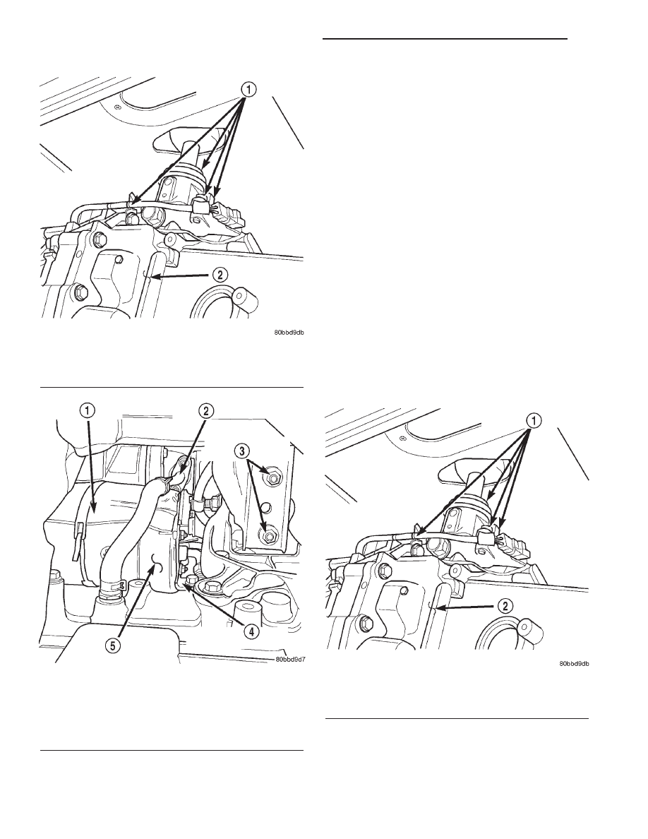
Fig. 12 Shifter Retaining Bolts

1 - SHIFTER ASSEMBLY RETAINING BOLTS
2 - TRANSMISSION

Fig. 13 Right Engine Mount Retaining Nuts

1 - STARTER MOTOR HEATSHIELD
2 - TURBOCHARGER OIL RETURN LINE
3 - RIGHT ENGINE MOUNT RETAINING NUTS
4 - STARTER MOTOR SUPPORT BRACKET
5 - STARTER MOTOR

Fig. 14 Shifter Retaining Bolts

1 - SHIFTER ASSEMBLY RETAINING BOLTS
2 - TRANSMISSION

9a - 18

ENGINE 2.5L VM DIESEL INTERNATIONAL

R1

ENGINE 2.5L VM DIESEL INTERNATIONAL (Continued)

(10) Install the transmission support crossmember.

Torque the bolts to 65 N·m (48 ft. lbs.).

(11) Install the fuelline support bracket on the

transmission support crossmember.

(12) Install the (4) transmission mount retaining

nuts on the transmission support crossmember (Fig.
15). Torque the nuts to 47 N·m (35 ft. lbs.).

(13) Install the clutch slave cylinder and the (2)

retaining nuts (Fig. 16). Torque the nuts to 40 N·m
(30 ft. lbs.).

(14) Install the exhaust system support bracket

nut on the transmission support crossmember (Fig.
15). Torque the nut to 67 N·m (50 ft. lbs.).

(15) Install the exhaust system support bracket

bolt in the clutch bellhousing. Torque the bolt to 88
N·m (65 ft. lbs.).

(16) Install the (2) exhaust system inlet pipe

retaining nuts. Torque the nuts to 36 N·m (27 ft.
lbs.).

(17) Install the propeller shaft assembly in the

vehicle. Install the (4) center bearing retaining nuts
and torque to 61 N·m (45 ft. lbs.).

(18) Remove the tape and position the rear univer-

sal joint in the rear axle companion flange. Install
the universal joint clamps and torque the retaining
bolts to 27 N·m (20 ft. lbs.).

(19) Lower the vehicle on the hoist.

(20) Install the body ground wire coming from the

negative battery cable end.

(21) Install the 12v feed wire coming from the pos-

itive battery cable end. Torque the nut to 12 N·m
(105 in. lbs.).

(22) Connect all remaining wiring coming from the

engine assembly in its original position.

(23) Install the lower radiator hose on the engine

assembly.

(24) Install the power steering fluid supply hose on

the power steering pump.

(25) Install the power steering fluid pressure line

on the power steering pump. Torque the nut to 28
N·m (21 ft. lbs.).

(26) Connect the power brake vacuum supply hose

on the engine assembly (Fig. 17).

(27) Install the fuel / water separator and mount-

ing bracket.

(28) Install the clutch fluid reservoir (Fig. 17).

Torque the nuts to 12 N·m (105 in. lbs.).

(29) Install and secure the fuel lines (Fig. 17) in

there original positions.

(30) Connect the electrical connectors to the bot-

tom of the fuel / water separator (Fig. 17).

(31) Connect the heater core coolant supply hoses

on the engine assembly.

(32) Install the fan shroud over the cooling fan.

Fig. 15 Transmission Mount Retaining Nuts

1 - EXHAUST SYSTEM SUPPORT BRACKET RETAINING NUT
2 - CROSSMEMBER
3 - TRANSMISSION
4 - TRANSMISSION MOUNT RETAINING NUTS

Fig. 16 Clutch Slave Cylinder

1 - SLAVE CYLINDER RETAINING NUTS
2 - HYDRAULIC CLUTCH SLAVE CYLINDER
3 - TRANSMISSION
4 - FLUID SUPPLY LINE

R1

ENGINE 2.5L VM DIESEL INTERNATIONAL

9a - 19

ENGINE 2.5L VM DIESEL INTERNATIONAL (Continued)

(33) Install the radiator and intercooler as an

assembly.

(34) Install the (2) upper fan shroud retaining

bolts (Fig. 18). Torque the bolts to 12 N·m (105 in.
lbs.).

(35) Install the intercooler inlet and outlet hoses.
(36) Connect the air intake hose on the turbo-

charger and install the air cleaner assembly.

(37) Install the upper radiator hose on the engine

(Fig. 18).

(38) Connect the coolant supply hoses on the cool-

ant reservoir (Fig. 19).

(39) Install the coolant reservoir on the bulkhead

(Fig. 19).

(40) Connect the coolant level sensor electrical con-

nector (Fig. 19).

(41) Connect the EGR solenoid vacuum line (Fig.

19).

(42) Connect the EGR solenoid electrical connector

(Fig. 19).

(43) Install the coolant hose on the water manifold

(Fig. 19).

(44) Install the coolant overflow hoses on the cool-

ant reservoir (Fig. 19).

Fig. 17 Fuel / Water Separator Position &

Orientation

1 - FUEL SUPPLY LINE (FROM TANK)
2 - HYDRAULIC CLUTCH FLUID RESERVOIR RETAINING NUTS
3 - FUEL/WATER SEPARATOR ASSEMBLY
4 - FUEL/WATER SEPARATOR ELECTRICAL CONNECTORS
5 - POWER BRAKE VACUUM SUPPLY HOSE
6 - FUEL SUPPLY LINE
7 - FUEL RETURN LINE (TO TANK)

Fig. 18 Upper Fan Shroud Retaining bolts

1 - UPPER RADIATOR SUPPORT RETAINING BOLTS
2 - FRONT CLOSURE PANEL
3 - UPPER FAN SHROUD RETAINING BOLTS
4 - UPPER RADIATOR HOSE

Fig. 19 Coolant Reservoir Position & Orientation

1 - EGR SOLENOID
2 - COOLANT RESERVOIR RETAINING BOLTS
3 - COOLANT OVERFLOW HOSES
4 - COOLANT LEVEL SENSOR
5 - COOLANT RESERVOIR
6 - COOLANT SUPPLY HOSES

9a - 20

ENGINE 2.5L VM DIESEL INTERNATIONAL

R1

ENGINE 2.5L VM DIESEL INTERNATIONAL (Continued)

(45) Position the refrigerant lines in the vehicle

and install the support bracket bolts in the generator
bracket and water manifold.

(46) Connect the refrigerant line at the A/C accu-

mulator (Fig. 20), making sure the sealing o-rings
are well lubricated with R134a oil and free of tears.
Install the secondary clip.

(47) Connect the refrigerant line at the A/C con-

denser (Fig. 21), making sure the sealing o-rings are
well lubricated with R134a oil and free of tears.
Install the secondary clip.

(48) Install the refrigerant line support bracket on

the A/C condenser.

(49) Install the A/C condenser support bolts in the

front closure panel. Torque the bolts to 22 N·m (200
in. lbs.).

(50) Install the upper radiator support (Fig. 22).

Torque the bolts to 33 N·m (25 ft. lbs.).

(51) Install the cowl grille (Fig. 23). (Refer to 23 -

BODY/EXTERIOR/COWL

GRILLE

-

INSTALLA-

TION).

(52) Raise the vehicle on the hoist.
(53) Install both refrigerant lines on the compres-

sor (Fig. 24), making sure the sealing o-rings are well
lubricated with R-134A refrigerant oil and free of
tears. Torque the bolts to 22 N·m (200 in. lbs.).

(54) Install the (2) lower fan shroud retaining

bolts. Torque the bolts to 12 N·m (105 in. lbs.).

(55) Install the lower radiator hose on the engine

assembly.

Fig. 20 Refrigerant Line At Accumulator

1 - EGR SOLENOID
2 - REFRIGERANT LINE AT A/C ACCUMULATOR

Fig. 21 Refrigerant Line At Accumulator

1 - FRONT CLOSURE PANEL
2 - HIGH PRESSURE REFRIGERANT LINE (FROM
COMPRESSOR)
3 - CONDENSER
4 - LIQUID REFRIGERANT LINE (TO EVAPORATOR)

Fig. 22 Upper Radiator Support

1 - UPPER RADIATOR SUPPORT RETAINING BOLTS
2 - FRONT CLOSURE PANEL
3 - UPPER FAN SHROUD RETAINING BOLTS
4 - UPPER RADIATOR HOSE

R1

ENGINE 2.5L VM DIESEL INTERNATIONAL

9a - 21

ENGINE 2.5L VM DIESEL INTERNATIONAL (Continued)


Content   ..  523  524  525  526   ..