Dodge Dakota (R1). Manual - part 513


  Index      Dodge     Dodge Dakota (R1) - service repair manual 2000 year


Search            


Content   ..  511  512  513  514   ..


Dodge Dakota (R1). Manual - part 513


Limits of taper or out-of-round on any crankshaft

journals should be held to 0.025 mm (0.001 in.).
Bearings are available in 0.025 mm (0.001 in.), 0.051
mm (0.002 in.), 0.076 mm (0.003 in.), 0.254 mm
(0.010 in.) and 0.305 mm (0.012 in.) undersize.
Install the bearings in pairs. DO NOT use a new
bearing half with an old bearing half. DO NOT
file the rods or bearing caps.

CRANKSHAFT

DESCRIPTION

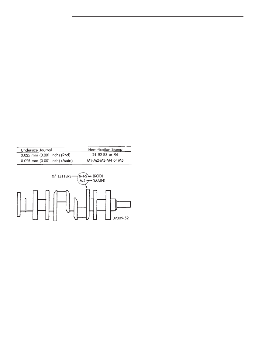
The crankshaft (Fig. 23) is of a cast nodular steel

splayed type design, with five main bearing journal-
s.The crankshaft is located at the bottom of the
engine block and is held in place with five main bear-
ing caps. The number 3 counterweight is the location
for journal size identification.

OPERATION

The crankshaft transfers force generated by com-

bustion within the cylinder bores to the flywheel or
flexplate.

REMOVAL

NOTE: This procedure can be done in vehicle. How-
ever the transmission must be removed first.

(1) If crankshaft is to be removed while engine is

in vehicle remove the transmission. Refer to 21 -
TRANSMISSION/TRANSAXLE.

(2) Remove the oil pan (Refer to 9 - ENGINE/LU-

BRICATION/OIL PAN - REMOVAL).

(3) Remove the oil pump from the rear main bear-

ing cap (Refer to 9 - ENGINE/LUBRICATION/OIL
PUMP - REMOVAL).

(4) Remove the vibration damper (Refer to 9 -

ENGINE/ENGINE BLOCK/VIBRATION DAMPER -
REMOVAL).

(5) Remove the timing chain cover (Refer to 9 -

ENGINE/VALVE TIMING/TIMING BELT / CHAIN
COVER(S) - REMOVAL).

(6) Identify

rod

bearing

caps

before

removal.

Remove rod bearing caps with bearings.

CAUTION:

Support

crankshaft

before

removing

main bearing caps. failure to do so will allow the
crankshaft to fall damaging the crankshaft.

(7) Using a suitable jack, support the crankshaft.
(8) Identify main bearing caps before removal.

Remove main bearing caps and bearings one at a
time.

(9) Lower the crankshaft out of the block.
(10) Remove and discard the crankshaft rear oil

seals.

(11) Remove and discard the front crankshaft oil

seal.

INSTALLATION

(1) Clean Gasket Maker residue and sealant from

the cylinder block and rear cap mating surface. Do
this before applying the Mopar

t Gasket Maker and

the installation of rear cap.

(2) Lightly oil the new upper seal lips with engine

oil.

(3) Install the new upper rear bearing oil seal with

the white paint facing towards the rear of the engine.

(4) Position the crankshaft into the cylinder block.
(5) Lightly oil the new lower seal lips with engine

oil.

(6) Install the new lower rear bearing oil seal into

the bearing cap with the white paint facing towards
the rear of the engine.

(7) Apply 5 mm (0.20 in) drop of Mopar

t Gasket

Maker, or equivalent, on each side of the rear main
bearing cap (Fig. 24). DO NOT over apply sealant or
allow the sealant to contact the rubber seal. Assem-
ble bearing cap to cylinder block immediately after
sealant application.

(8) To align the bearing cap, use cap slot, align-

ment dowel and cap bolts. DO NOT remove excess
material after assembly. DO NOT strike rear cap
more than 2 times for proper engagement.

(9) Clean and oil all cap bolts. Install all main

bearing caps. Install all cap bolts and alternately
tighten to 115 N·m (85 ft. lbs.) torque.

(10) Install oil pump (Refer to 9 - ENGINE/LU-

BRICATION/OIL PUMP - INSTALLATION).

(11) Install the timing chain cover (Refer to 9 -

ENGINE/VALVE TIMING/TIMING BELT / CHAIN
COVER(S) - INSTALLATION).

Fig. 23 Crankshaft with Journal Size Identification

9 - 240

ENGINE 5.9L

AN

CONNECTING ROD BEARINGS (Continued)

(12) Install the vibration damper (Refer to 9 -

ENGINE/ENGINE BLOCK/VIBRATION DAMPER -
INSTALLATION).

(13) Position the connecting rods onto the crank-

shaft and install the rod bearing caps. Tighten the
nuts to 61 N·m (45 ft. lbs.).

(14) Apply Mopar

t Silicone Rubber Adhesive Seal-

ant, or equivalent, at bearing cap to block joint to
provide cap to block and oil pan sealing (Fig. 25).
Apply enough sealant until a small amount is
squeezed out. Withdraw nozzle and wipe excess seal-
ant off the oil pan seal groove.

(15) Install new front crankshaft oil seal (Refer to

9 - ENGINE/ENGINE BLOCK/CRANKSHAFT OIL
SEAL - FRONT - INSTALLATION).

(16) Immediately install the oil pan (Refer to 9 -

ENGINE/LUBRICATION/OIL

PAN

-

INSTALLA-

TION).

(17) If the transmission was removed, install the

transmission. Refer to 21 - TRANSMISSION/TRAN-
SAXLE.

CRANKSHAFT MAIN
BEARINGS

DESCRIPTION

Main bearings (Fig. 26) are located in the cylinder

block. One half of the main bearing is located in the
crankshaft main bore the other half of the matching
bearing is located in the main bearing cap. there are
five main bearings. Number three main bearing is
flanged, this flange controls crankshaft thrust.

OPERATION

The main bearings encircle the crankshaft main

bearing journals, this aligns the crankshaft to the

centerline of the engine and allows the crankshaft to
turn without wobbling or shaking therefore eliminat-
ing vibration. The main bearings are available in
standard and undersizes.

STANDARD PROCEDURE—CRANKSHAFT MAIN
BEARING FITTING

Bearing caps are not interchangeable and should

be marked at removal to ensure correct assembly.
Upper and lower bearing halves are NOT inter-
changeable. Lower main bearing halves of No.2 and 4
are interchangeable.

Upper and lower No.3 bearing halves are flanged

to carry the crankshaft thrust loads. They are NOT
interchangeable with any other bearing halves in the
engine (Fig. 27). Bearing shells are available in stan-
dard and the following undersizes: Never install an

Fig. 24 Sealant Application to Bearing Cap

1 - .25 DROP OF LOCTITE 515 ON BOTH SIDES OF REAR MAIN
CAP

Fig. 25 Apply Sealant to Bearing Cap to Block Joint

1 - MOPAR

T

GEN II SILICONE RUBBER ADHESIVE SEALANT

NOZZLE TIP
2 - SEALANT APPLIED
3 - CYLINDER BLOCK
4 - REAR MAIN BEARING CAP

Fig. 26 Main Bearing Orientation

AN

ENGINE 5.9L

9 - 241

CRANKSHAFT (Continued)

undersize bearing that will reduce clearance below
specifications.

Main Bearing Undersize Availability List

• 0.25 mm (0.001 inch)

• 0.051 mm (0.002 inch)

• 0.076 mm (0.003 inch)

• 0.254 mm (0.010 inch)

• 0.305 mm (0.012 inch)

REMOVAL

(1) Remove the oil pan (Refer to 9 - ENGINE/LU-

BRICATION/OIL PAN - REMOVAL).

(2) Remove the oil pump from the rear main bear-

ing cap (Refer to 9 - ENGINE/LUBRICATION/OIL
PUMP - REMOVAL).

(3) Identify bearing caps before removal. Remove

bearing caps one at a time.

(4) Remove upper half of bearing by inserting

Crankshaft Main Bearing Remover/Installer Tool
C-3059 into the oil hole of crankshaft (Fig. 28).

(5) Slowly rotate crankshaft clockwise, forcing out

upper half of bearing shell.

INSTALLATION

Only one main bearing should be selectively fitted

while all other main bearing caps are properly tight-
ened. All bearing capbolts removed during service
procedures are to be cleaned and oiled before instal-
lation.

When installing a new upper bearing shell, slightly

chamfer the sharp edges from the plain side.

(1) Start bearing in place, and insert Crankshaft

Main Bearing Remover/Installer Tool C-3059 into oil
hole of crankshaft (Fig. 28).

(2) Slowly rotate crankshaft counterclockwise slid-

ing the bearing into position. Remove Tool C-3059.

(3) Install the bearing caps. Clean and oil the

bolts. Tighten the capbolts to 115 N·m (85 ft. lbs.)
torque.

(4) Install the oil pump (Refer to 9 - ENGINE/LU-

BRICATION/OIL PUMP - INSTALLATION).

(5) Install the oil pan (Refer to 9 - ENGINE/LU-

BRICATION/OIL PAN - INSTALLATION).

(6) Start engine check for leaks.

CRANKSHAFT OIL SEAL -
FRONT

DESCRIPTION

The crankshaft front seal is a one piece viton seal

with a steel housing. The front seal is located in the
engine front cover.

OPERATION

The crankshaft seals prevent oil from leaking from

around the crankshaft, either from the rear of the
engine or from the engine front cover.

REMOVAL

The oil seal can be replaced without removing the

timing chain cover, provided that the cover is not
misaligned.

(1) Disconnect the negative cable from the battery.
(2) Remove

vibration

damper

(Refer

to

9

-

ENGINE/ENGINE BLOCK/VIBRATION DAMPER -
REMOVAL).

Fig. 27 Main Bearing

Fig. 28 Upper Main Bearing Removal and

Installation with Tool C-3059

1 - SPECIAL TOOL C-3059
2 - BEARING
3 - SPECIAL TOOL C-3059
4 - BEARING

9 - 242

ENGINE 5.9L

AN

CRANKSHAFT MAIN BEARINGS (Continued)

(3) If front seal is suspected of leaking, check front

oil seal alignment to crankshaft. The seal installa-
tion/alignment Tool 6635, should fit with minimum
interference. If tool does not fit, the cover must be
removed and installed properly.

(4) Place a suitable tool behind the lips of the oil

seal to pry the oil seal outward. Be careful not to
damage the crankshaft seal bore of cover.

INSTALLATION

(1) Place the smaller diameter of the oil seal over

Front Oil Seal Installation Tool 6635 (Fig. 29) . Seat
the oil seal in the groove of the tool.

(2) Position the seal and tool onto the crankshaft

(Fig. 30).

(3) Using the vibration damper bolt, tighten the

bolt to draw the seal into position on the crankshaft
(Fig. 31).

(4) Remove the vibration damper bolt and seal

installation tool.

(5) Inspect

the

seal

flange

on

the

vibration

damper.

(6) Install the vibration damper (Refer to 9 -

ENGINE/ENGINE BLOCK/VIBRATION DAMPER -
INSTALLATION).

(7) Connect the negative cable to the battery.

CRANKSHAFT OIL SEAL -
REAR

DESCRIPTION

The crankshaft rear seal is a two piece viton seal.

One part of the two piece rear seal is located in a slot
in the cylinder block oppsite the crankshaft main
bearing cap, the second part of the two piece seal is
located in the main bearing cap itself.

Fig. 29 Placing Oil Seal on Installation Tool 6635

1 - CRANKSHAFT FRONT OIL SEAL
2 - INSTALL THIS END INTO SPECIAL TOOL 6635

Fig. 30 Position Tool and Seal onto Crankshaft

1 - SPECIAL TOOL 6635
2 - OIL SEAL
3 - TIMING CHAIN COVER

Fig. 31 Installing Oil Seal

1 - SPECIAL TOOL 6635
2 - TIMING CHAIN COVER

AN

ENGINE 5.9L

9 - 243

CRANKSHAFT OIL SEAL - FRONT (Continued)


Content   ..  511  512  513  514   ..