Dodge Dakota (R1). Manual - part 511


  Index      Dodge     Dodge Dakota (R1) - service repair manual 2000 year


Search            


Content   ..  509  510  511  512   ..


Dodge Dakota (R1). Manual - part 511


(8) Disconnect

accelerator

linkage

and

if

so

equipped, the speed control and transmission kick-
down cables.

(9) Remove distributor cap and wires.
(10) Disconnect the coil wires.
(11) Disconnect heat indicator sending unit wire.
(12) Disconnect heater hoses and bypass hose.
(13) Remove cylinder head covers and gaskets

(Refer to 9 - ENGINE/CYLINDER HEAD/CYLIN-
DER HEAD COVER(S) - REMOVAL).

(14) Remove

intake

manifold

(Refer

to

9

-

ENGINE/MANIFOLDS/INTAKE

MANIFOLD

-

REMOVAL) and throttle body as an assembly. Dis-
card the flange side gaskets and the front and rear
cross-over gaskets.

(15) Remove exhaust manifolds (Refer to 9 -

ENGINE/MANIFOLDS/EXHAUST

MANIFOLD

-

REMOVAL).

(16) Remove rocker arm assemblies and push rods.

Identify to ensure installation in original locations.

(17) Remove the head bolts from each cylinder

head and remove cylinder heads. Discard the cylin-
der head gasket.

(18) Remove spark plugs.

CLEANING

Clean all surfaces of cylinder block and cylinder

heads.

Clean cylinder block front and rear gasket surfaces

using a suitable solvent.

INSPECTION

Inspect all surfaces with a straightedge if there is

any reason to suspect leakage. If out-of-flatness
exceeds

0.00075mm/mm

(0.0001in./in.)

times

the

span length in any direction, either replace head or
lightly machine the head surface.

FOR EXAMPLE:—A 305 mm (12 in.) span is

0.102 mm (0.004 in.) out-of-flat. The allowable out-of-
flat is 305 x 0.00075 (12 x 0.00075) equals 0.23 mm
(0.009 in.). This amount of out-of-flat is acceptable.

The

cylinder

head

surface

finish

should

be

1.78-3.00 microns (70-125 microinches).

Inspect push rods. Replace worn or bent rods.

INSTALLATION

(1) Clean all surfaces of cylinder block and cylin-

der heads.

(2) Clean cylinder block front and rear gasket sur-

faces using a suitable solvent.

(3) Position new cylinder head gaskets onto the

cylinder block.

(4) Position cylinder heads onto head gaskets and

cylinder block.

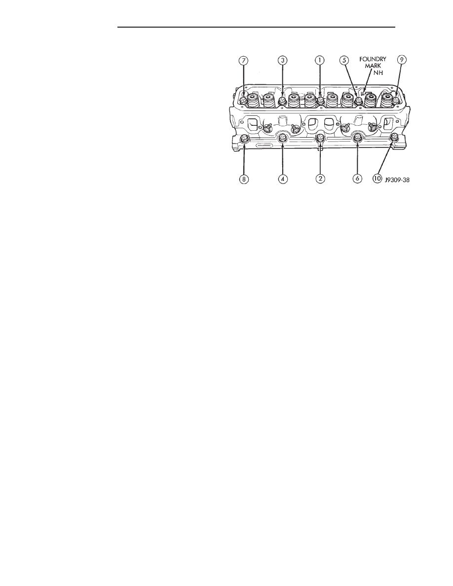
(5) Starting at top center, tighten all cylinder head

bolts, in sequence (Fig. 6).

CAUTION: When tightening the rocker arm bolts,
make sure the piston in that cylinder is NOT at
TDC. Contact between the valves and piston could
occur.

(6) Install push rods and rocker arm assemblies in

their original position. Tighten the bolts to 28 N·m
(21 ft. lbs.) torque.

(7) Install the intake manifold (Refer to 9 -

ENGINE/MANIFOLDS/INTAKE

MANIFOLD

-

INSTALLATION) and throttle body assembly.

(8) Install

exhaust

manifolds

(Refer

to

9

-

ENGINE/MANIFOLDS/EXHAUST

MANIFOLD

-

INSTALLATION).

(9) If required, adjust spark plugs to specifications.

Install the plugs and tighten to 41 N·m (30 ft. lbs.)
torque.

(10) Install coil wire.
(11) Connect heat indicator sending unit wire.
(12) Connect the heater hoses and bypass hose.
(13) Install distributor cap and wires.
(14) Connect the accelerator linkage and if so

equipped, the speed control and transmission kick-
down cables.

(15) Install the fuel supply line (Refer to 14 -

FUEL

SYSTEM/FUEL

DELIVERY/QUICK

CON-

NECT FITTING - STANDARD PROCEDURE).

(16) Install the generator and drive belt (Refer to 7

- COOLING/ACCESSORY DRIVE/DRIVE BELTS -
INSTALLATION). Tighten generator mounting bolt
to 41 N·m (30 ft. lbs.) torque. Tighten the adjusting
strap bolt to 23 N·m (200 in. lbs.) torque.

(17) Install

the

intake

manifold-to-generator

bracket support rod. Tighten the bolts.

(18) Place the cylinder head cover gaskets in posi-

tion and install cylinder head covers (Refer to 9 -
ENGINE/CYLINDER

HEAD/CYLINDER

HEAD

COVER(S) - INSTALLATION).

(19) Install closed crankcase ventilation system.

Fig. 6 Cylinder Head Bolt Tightening Sequence

9 - 232

ENGINE 5.9L

AN

CYLINDER HEAD (Continued)

(20) Connect the evaporation control system.
(21) Install the air cleaner.
(22) Fill cooling system (Refer to 7 - COOLING -

STANDARD PROCEDURE).

(23) Connect the negative cable to the battery.
(24) Start engine check for leaks.

CYLINDER HEAD COVER(S)

DESCRIPTION - CYLINDER HEAD COVER
GASKET

The cylinder head cover gasket (Fig. 7) is a steel-

backed silicone gasket, designed for long life usage.

OPERATION - CYLINDER HEAD COVER
GASKET

The steel-backed silicone gasket is designed to seal

the cylinder head cover for long periods of time
through extensive heat and cold, without failure. The
gasket is designed to be reusable.

REMOVAL

NOTE: A steel backed silicon gasket is used with
the cylinder head cover (Fig. 8). This gasket can be
used again.

(1) Disconnect the negative cable from the battery.
(2) Disconnect the spark plug wires form the spark

plugs and set aside.

(3) Disconnect closed ventilation system and evap-

oration control system from cylinder head cover.

(4) Remove cylinder head cover and gasket.

CLEANING

Clean cylinder head cover gasket surface.
Clean head rail, if necessary.

INSPECTION

Inspect cover for distortion and straighten, if nec-

essary.

Check the gasket for use in head cover installation.

If damaged, use a new gasket.

INSTALLATION

(1) The cylinder head cover gasket can be used

again. Install the gasket onto the head rail.

(2) Position the cylinder head cover onto the gas-

ket. Tighten the bolts to 11 N·m (95 in. lbs.) torque.

(3) Install closed crankcase ventilation system and

evaporation control system.

(4) Connect the spark plug wires to the spark

plugs.

(5) Connect the negative cable to the battery.

INTAKE/EXHAUST VALVES &
SEATS

DESCRIPTION

Both the intake and exhaust valves are made of

steel. The intake valve is 48.768 mm (1.92 inches) in
diameter and the exhaust valve is 41.148 mm (1.62
inches) in diameter and has a 2.032 mm (0.080 inch)
wafer interia welded to the tip for durability. These
valves are not splayed.

STANDARD PROCEDURE—VALVES, GUIDES
AND SPRINGS

VALVE CLEANING

Clean valves thoroughly. Discard burned, warped,

or cracked valves.

Remove carbon and varnish deposits from inside of

valve guides with a reliable guide cleaner.

VALVE GUIDES

Measure valve stems for wear. If wear exceeds

0.051 mm (0.002 in.), replace the valve.

Measure valve stem guide clearance as follows:
(1) Install Valve Guide Sleeve Tool C-3973 over

valve stem and install valve (Fig. 9). The special

Fig. 7 Cylinder Head Cover Gasket V-8 Gas Engines

1 - CYLINDER HEAD COVER GASKET

Fig. 8 Cylinder Head Cover Gasket

1 - CYLINDER HEAD COVER GASKET

AN

ENGINE 5.9L

9 - 233

CYLINDER HEAD (Continued)

sleeve places the valve at the correct height for
checking with a dial indicator.

(2) Attach dial indicator Tool C-3339 to cylinder

head and set it at right angles to valve stem being
measured (Fig. 10).

(3) Move valve to and from the indicator. The total

dial indicator reading should not exceed 0.432 mm
(0.017 in.). Ream the guides for valves with oversize
stems if dial indicator reading is excessive or if the
stems are scuffed or scored.

VALVE GUIDES

Service valves with oversize stems are available.

Refer to REAMER SIZES CHART

REAMER SIZES CHART

REAMER O/S

VALVE GUIDE SIZE

0.076 mm

8.026 - 8.052 mm

(0.003 in.)

(0.316 - 0.317 in.)

0.381 mm

8.331 - 8.357 mm

(0.015 in.)

(0.328 - 0.329 in.)

(1) Slowly turn reamer by hand and clean guide

thoroughly before installing new valve. Ream the
valve guides from standard to 0.381 mm (0.015
in.). Use a two step procedure so the valve
guides are reamed true in relation to the valve
seat:

• Step 1—Ream to 0.0763 mm (0.003 inch).

• Step 2—Ream to 0.381 mm (0.015 inch).

REFACING VALVES AND VALVE SEATS

The intake and exhaust valves have a 43-1/4° to

43-3/4° face angle and a 44-1/4° to 44-3/4° seat angle
(Fig. 11).

Fig. 9 Positioning Valve with Tool C-3973

1 - VALVE
2 - SPACER TOOL

Fig. 10 Measuring Valve Guide Wear

1 - VALVE
2 - SPECIAL TOOL C-3339

Fig. 11 Valve Face and Seat Angles

1 - CONTACT POINT
A,B,C and D Refer to VALVE FACE AND VALVE SEAT ANGLE
CHART

9 - 234

ENGINE 5.9L

AN

INTAKE/EXHAUST VALVES & SEATS (Continued)

VALVE FACE AND VALVE SEAT ANGLE CHART

ITEM

DESCRIPTION

SPECIFICATION

A

SEAT WIDTH

INTAKE

1.016 - 1.524 mm

(0.040 - 0.060 in.)

EXHAUST

1.524 - 2.032 mm

(0.060 - 0.080 in.)

B

FACE ANGLE

(INT. AND EXT.)

43¼° - 43¾°

C

SEAT ANGLE

(INT. AND EXT.)

44¼° - 44¾°

D

CONTACT

SURFACE

VALVES

Inspect the remaining margin after the valves are

refaced (Fig. 12). Valves with less than 1.190 mm
(0.047 in.) margin should be discarded.

VALVE SEATS

CAUTION: DO NOT un-shroud valves during valve
seat refacing (Fig. 13).

(1) When refacing valve seats, it is important that

the correct size valve guide pilot be used for reseating
stones. A true and complete surface must be obtained.

(2) Measure the concentricity of valve seat using a

dial indicator. Total runout should not exceed 0.051
mm (0.002 in.) total indicator reading.

(3) Inspect the valve seat with Prussian blue, to

determine where the valve contacts the seat. To do
this, coat valve seat LIGHTLY with Prussian blue
then set valve in place. Rotate the valve with light
pressure. If the blue is transferred to the center of
valve face, contact is satisfactory. If the blue is trans-
ferred to the top edge of valve face, lower valve seat
with a 15° stone. If the blue is transferred to bottom
edge of valve face raise valve seat with a 60° stone.

(4) When seat is properly positioned the width of

intake seats should be 1.016-1.524 mm (0.040-0.060
in.). The width of the exhaust seats should be 1.524-
2.032 mm (0.060-0.080 in.).

VALVE SPRINGS

Whenever valves have been removed for inspection,

reconditioning or replacement, valve springs should
be tested. As an example the compression length of
the spring to be tested is 1-5/16 in.. Turn table of
Universal Valve Spring Tester Tool until surface is in
line with the 1-5/16 in. mark on the threaded stud.
Be sure the zero mark is to the front (Fig. 14). Place
spring over stud on the table and lift compressing
lever to set tone device. Pull on torque wrench until
ping is heard. Take reading on torque wrench at this
instant. Multiply this reading by 2. This will give the
spring load at test length. Fractional measurements
are indicated on the table for finer adjustments.
Refer to specifications to obtain specified height and
allowable tensions. Discard the springs that do not
meet specifications.

Fig. 12 Intake and Exhaust Valves

1 - MARGIN
2 - VALVE SPRING RETAINER LOCK GROOVE
3 - STEM
4 - FACE

Fig. 13 Refacing Valve Seats

1 - STONE
2 - PILOT
3 - VALVE SEAT
4 - SHROUD

AN

ENGINE 5.9L

9 - 235

INTAKE/EXHAUST VALVES & SEATS (Continued)


Content   ..  509  510  511  512   ..