Dodge Dakota (R1). Manual - part 508


  Index      Dodge     Dodge Dakota (R1) - service repair manual 2000 year


Search            


Content   ..  506  507  508  509   ..


Dodge Dakota (R1). Manual - part 508


(6) Record the compression pressure on the third

revolution. Continue the test for the remaining cylin-
ders.

(Refer to 9 - ENGINE - SPECIFICATIONS) for the

correct engine compression pressures.

DIAGNOSIS AND TESTING—CYLINDER
COMBUSTION PRESSURE LEAKAGE

The combustion pressure leakage test provides an

accurate means for determining engine condition.

Combustion pressure leakage testing will detect:
• Exhaust and intake valve leaks (improper seat-

ing)

• Leaks between adjacent cylinders or into water

jacket

• Any causes for combustion/compression pressure

loss

WARNING: DO NOT REMOVE THE RADIATOR CAP
WITH THE SYSTEM HOT AND UNDER PRESSURE.
SERIOUS

BURNS

FROM

HOT

COOLANT

CAN

OCCUR.

Check the coolant level and fill as required. DO

NOT install the radiator cap.

Start and operate the engine until it attains nor-

mal operating temperature, then turn OFF the
engine.

Remove the spark plugs.
Remove the oil filler cap.
Remove the air cleaner.
Calibrate the tester according to the manufactur-

er’s instructions. The shop air source for testing
should maintain 483 kPa (70 psi) minimum, 1,379
kPa (200 psi) maximum and 552 kPa (80 psi) recom-
mended.

Perform the test procedure on each cylinder accord-

ing to the tester manufacturer’s instructions. While
testing, listen for pressurized air escaping through
the throttle body, tailpipe or oil filler cap opening.
Check for bubbles in the radiator coolant.

All gauge pressure indications should be equal,

with no more than 25% leakage.

FOR EXAMPLE: At 552 kPa (80 psi) input pres-

sure, a minimum of 414 kPa (60 psi) should be main-
tained in the cylinder.

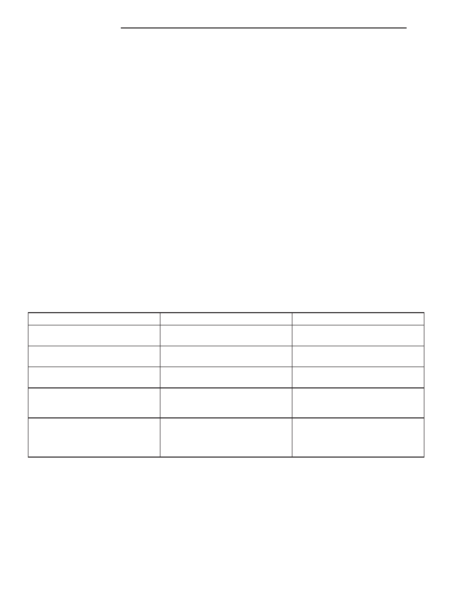
Refer to CYLINDER COMBUSTION PRESSURE

LEAKAGE DIAGNOSIS CHART below

CYLINDER COMBUSTION PRESSURE LEAKAGE DIAGNOSIS CHART

CONDITION

POSSIBLE CAUSE

CORRECTION

AIR ESCAPES THROUGH
THROTTLE BODY

Intake valve bent, burnt, or not
seated properly

Inspect valve and valve seat.
Reface or replace, as necessary

AIR ESCAPES THROUGH
TAILPIPE

Exhaust valve bent, burnt, or not
seated properly

Inspect valve and valve seat.
Reface or replace, as necessary

AIR ESCAPES THROUGH
RADIATOR

Head gasket leaking or cracked
cylinder head or block

Remove cylinder head and inspect.
Replace defective part

MORE THAN 50% LEAKAGE
FROM ADJACENT CYLINDERS

Head gasket leaking or crack in
cylinder head or block between
adjacent cylinders

Remove cylinder head and inspect.
Replace gasket, head, or block as
necessary

MORE THAN 25% LEAKAGE AND
AIR ESCAPES THROUGH OIL
FILLER CAP OPENING ONLY

Stuck or broken piston rings;
cracked piston; worn rings and/or
cylinder wall

Inspect for broken rings or piston.
Measure ring gap and cylinder
diameter, taper and out-of-round.
Replace defective part as necessary

9 - 220

ENGINE 5.9L

AN

ENGINE 5.9L (Continued)

STANDARD PROCEDURE - FORM-IN-PLACE
GASKETS AND SEALERS

There are numerous places where form-in-place

gaskets are used on the engine. Care must be taken
when

applying

form-in-place

gaskets

to

assure

obtaining the desired results. Do not use form-in-
place gasket material unless specified. 
Bead size,
continuity, and location are of great importance. Too
thin a bead can result in leakage while too much can
result in spill-over which can break off and obstruct
fluid feed lines. A continuous bead of the proper
width is essential to obtain a leak-free gasket.

There are numerous types of form-in-place gasket

materials that are used in the engine area. Mopar

t

Engine RTV GEN II, Mopar

t ATF-RTV, and Mopart

Gasket Maker gasket materials, each have different
properties and can not be used in place of the other.

MOPAR

ENGINE RTV GEN II

Mopar

t Engine RTV GEN II is used to seal com-

ponents exposed to engine oil. This material is a spe-
cially designed black silicone rubber RTV that
retains

adhesion

and

sealing

properties

when

exposed to engine oil. Moisture in the air causes the
material to cure. This material is available in three
ounce tubes and has a shelf life of one year. After one
year this material will not properly cure. Always
inspect the package for the expiration date before
use.

MOPAR

ATF RTV

Mopar

t ATF RTV is a specifically designed black

silicone rubber RTV that retains adhesion and seal-
ing properties to seal components exposed to auto-
matic

transmission

fluid,

engine

coolants,

and

moisture. This material is available in three ounce
tubes and has a shelf life of one year. After one year
this material will not properly cure. Always inspect
the package for the expiration date before use.

MOPAR

GASKET MAKER

Mopar

t Gasket Maker is an anaerobic type gasket

material. The material cures in the absence of air
when squeezed between two metallic surfaces. It will
not cure if left in the uncovered tube. The anaerobic
material is for use between two machined surfaces.
Do not use on flexible metal flanges.

MOPAR

GASKET SEALANT

Mopar

t Gasket Sealant is a slow drying, perma-

nently soft sealer. This material is recommended for
sealing threaded fittings and gaskets against leakage
of oil and coolant. Can be used on threaded and
machined parts under all temperatures. This mate-
rial is used on engines with multi-layer steel (MLS)
cylinder head gaskets. This material also will pre-
vent corrosion. Mopar

t Gasket Sealant is available in

a 13 oz. aerosol can or 4oz./16 oz. can w/applicator.

FORM-IN-PLACE GASKET AND SEALER
APPLICATION

Assembling parts using a form-in-place gasket

requires care but it’s easier then using precut gas-
kets.

Mopar

t Gasket Maker material should be applied

sparingly 1 mm (0.040 in.) diameter or less of sealant
to one gasket surface. Be certain the material sur-
rounds each mounting hole. Excess material can eas-
ily be wiped off. Components should be torqued in
place within 15 minutes. The use of a locating dowel
is recommended during assembly to prevent smear-
ing material off the location.

Mopar

t Engine RTV GEN II or ATF RTV gasket

material should be applied in a continuous bead
approximately 3 mm (0.120 in.) in diameter. All
mounting holes must be circled. For corner sealing, a
3.17 or 6.35 mm (1/8 or 1/4 in.) drop is placed in the
center of the gasket contact area. Uncured sealant
may be removed with a shop towel. Components
should be torqued in place while the sealant is still
wet to the touch (within 10 minutes). The usage of a
locating dowel is recommended during assembly to
prevent smearing material off the location.

Mopar

t Gasket Sealant in an aerosol can should be

applied using a thin, even coat sprayed completely
over both surfaces to be joined, and both sides of a
gasket. Then proceed with assembly. Material in a
can w/applicator can be brushed on evenly over the
sealing surfaces. Material in an aerosol can should be
used on engines with multi-layer steel gaskets.

STANDARD PROCEDURE - REPAIR DAMAGED
OR WORN THREADS

CAUTION: Be sure that the tapped holes maintain
the original center line.

Damaged or worn threads can be repaired. Essen-

tially, this repair consists of:

• Drilling out worn or damaged threads.

• Tapping the hole with a special Heli-Coil Tap, or

equivalent.

• Installing an insert into the tapped hole to bring

the hole back to its original thread size.

STANDARD PROCEDURE—HYDROSTATIC
LOCK

CAUTION: DO NOT use the starter motor to rotate
the crankshaft. Severe damage could occur.

When an engine is suspected of hydrostatic lock

(regardless of what caused the problem), follow the
steps below.

AN

ENGINE 5.9L

9 - 221

ENGINE 5.9L (Continued)

(1) Perform the Fuel Pressure Release Procedure

(Refer to 14 - FUEL SYSTEM/FUEL DELIVERY -
STANDARD PROCEDURE).

(2) Disconnect the negative cable(s) from the bat-

tery.

(3) Inspect air cleaner, induction system, and

intake manifold to ensure system is dry and clear of
foreign material.

(4) Place a shop towel around the spark plugs to

catch any fluid that may possibly be under pressure
in the cylinder head. Remove the spark plugs.

(5) With all spark plugs removed, rotate the crank-

shaft using a breaker bar and socket.

(6) Identify the fluid in the cylinders (coolant, fuel,

oil, etc.).

(7) Be sure all fluid has been removed from the

cylinders.

(8) Repair engine or components as necessary to

prevent this problem from occurring again.

(9) Squirt a small amount of engine oil into the

cylinders to lubricate the walls. This will prevent
damage on restart.

(10) Install new spark plugs. Tighten the spark

plugs to 41 N·m (30 ft. lbs.) torque.

(11) Drain engine oil. Remove and discard the oil

filter.

(12) Install the drain plug. Tighten the plug to 34

N·m (25 ft. lbs.) torque.

(13) Install a new oil filter.
(14) Fill

engine

crankcase

with

the

specified

amount and grade of oil. (Refer to LUBRICATION &
MAINTENANCE - SPECIFICATIONS).

(15) Connect the negative cable(s) to the battery.
(16) Start the engine and check for any leaks.

STANDARD PROCEDURE—CYLINDER BORE
HONING

Before honing, stuff plenty of clean shop towels

under the bores and over the crankshaft to keep
abrasive materials from entering the crankshaft
area.

(1) Used carefully, the Cylinder Bore Sizing Hone

C-823, equipped with 220 grit stones, is the best tool
for this job. In addition to deglazing, it will reduce
taper and out-of-round, as well as removing light
scuffing, scoring and scratches. Usually, a few strokes
will clean up a bore and maintain the required lim-
its.

CAUTION: DO NOT use rigid type hones to remove
cylinder wall glaze.

(2) Deglazing of the cylinder walls may be done if

the cylinder bore is straight and round. Use a cylin-
der surfacing hone, Honing Tool C-3501, equipped
with 280 grit stones (C-3501-3810). about 20-60

strokes, depending on the bore condition, will be suf-
ficient to provide a satisfactory surface. Using honing
oil C-3501-3880, or a light honing oil, available from
major oil distributors.

CAUTION: DO NOT use engine or transmission oil,
mineral spirits, or kerosene.

(3) Honing should be done by moving the hone up

and down fast enough to get a crosshatch pattern.
The hone marks should INTERSECT at 40° to 60°
for proper seating of rings (Fig. 3).

(4) A controlled hone motor speed between 200 and

300 RPM is necessary to obtain the proper cross-
hatch angle. The number of up and down strokes per
minute can be regulated to get the desired 40° to 60°
angle. Faster up and down strokes increase the cross-
hatch angle.

(5) After honing, it is necessary that the block be

cleaned to remove all traces of abrasive. Use a brush
to wash parts with a solution of hot water and deter-
gent. Dry parts thoroughly. Use a clean, white, lint-
free cloth to check that the bore is clean. Oil the
bores after cleaning to prevent rusting.

REMOVAL

(1) Scribe hood hinge outlines on hood. Remove the

hood.

(2) Remove the battery.
(3) Drain cooling system. (Refer to 7 - COOLING -

STANDARD PROCEDURE).

(4) Remove the air cleaner, air in-let hose and res-

onator assembly.

(5) Disconnect the radiator and heater hoses.

Remove radiator. (Refer to 7 - COOLING/ENGINE/
RADIATOR - REMOVAL).

Fig. 3 Cylinder Bore Crosshatch Pattern

1 - CROSSHATCH PATTERN
2 - INTERSECT ANGLE

9 - 222

ENGINE 5.9L

AN

ENGINE 5.9L (Continued)

(6) Disconnect the vacuum lines from the intake

manifold.

(7) Remove the distributor cap and wiring.
(8) Disconnect the accelerator linkage (Refer to 14

- FUEL SYSTEM/FUEL INJECTION/THROTTLE
CONTROL CABLE - REMOVAL).

(9) Remove throttle body (Refer to 14 - FUEL SYS-

TEM/FUEL

INJECTION/THROTTLE

BODY

-

REMOVAL).

(10) Perform the Fuel System Pressure Release

procedure (Refer to 14 - FUEL SYSTEM/FUEL
DELIVERY - STANDARD PROCEDURE).

(11) Disconnect the starter wires.
(12) Disconnect the oil pressure wire.
(13) Discharge the air conditioning system, if

equipped. (Refer to 24 - HEATING & AIR CONDI-
TIONING/PLUMBING/REFRIGERANT

-

STAN-

DARD PROCEDURE).

(14) Disconnect the air conditioning hoses.
(15) Disconnect

the

power

steering

hoses,

if

equipped.

(16) Remove starter motor (Refer to 8 - ELECTRI-

CAL/STARTING/STARTER MOTOR - REMOVAL).

(17) Remove the generator (Refer to 8 - ELECTRI-

CAL/CHARGING/GENERATOR - REMOVAL).

(18) Raise and support the vehicle on a hoist.
(19) Disconnect exhaust pipe at manifolds.
(20) RemoveTransmission. Refer to 21 - TRANS-

MISSION AND TRANSFER CASE.

CAUTION: DO NOT lift the engine by the intake
manifold.

(21) Install an engine lifting fixture.
(22)

2WD VEHICLES—Remove engine front

mount bolts.

(23) 4WD

VEHICLES—The

engine

and

front

driving axle (engine/axle/transmission) are connected
through insulators and support brackets. Separate
the engine as follows:

• LEFT SIDE—Remove 2 bolts attaching (engine/

pinion nose/transmission) bracket to transmission
bell housing. Remove 2 bracket to pinion nose adap-
tor bolts. Separate engine from insulator by removing
upper nut washer assembly and bolt from engine
support bracket.

• RIGHT SIDE—Remove 2 bracket to axle (dis-

connect housing) bolts and 1 bracket to bell housing
bolt. Separate engine from insulator by removing
upper nut washer assembly and bolt from engine
support bracket.

(24) Lower the vehicle.
(25) On automatic transmission vehicles, discon-

nect the engine from the torque converter drive plate.
On manual transmission vehicles, move engine for-
ward until drive pinion shaft clears the clutch disc.
Remove engine from engine compartment.

(26) Install engine assembly on engine repair

stand.

INSTALLATION

(1) Remove engine from the repair stand and posi-

tion in the engine compartment.

(2) Install an engine support fixture.
(3) Raise and support the vehicle on a hoist.
(4) Install transmission.
(5) Install the front engine mounts (Refer to 9 -

ENGINE/ENGINE MOUNTING/FRONT MOUNT -
INSTALLATION).

(6) Install exhaust pipe to manifold.
(7) Lower the vehicle.
(8) Remove engine lifting fixture.
(9) Install the generator (Refer to 8 - ELECTRI-

CAL/CHARGING/GENERATOR - INSTALLATION).

(10) Install starter motor (Refer to 8 - ELECTRI-

CAL/STARTING/STARTER MOTOR - INSTALLA-
TION).

(11) Connect power steering hoses, if equipped.
(12) Connect air conditioning hoses.
(13) Evacuate and charge the air conditioning sys-

tem, if equipped (Refer to 24 - HEATING & AIR
CONDITIONING/PLUMBING/REFRIGERANT

-

STANDARD PROCEDURE).

(14) Using a new gasket, install throttle body

(Refer to 14 - FUEL SYSTEM/FUEL INJECTION/
THROTTLE BODY - INSTALLATION).

(15) Connect the accelerator linkage (Refer to 14 -

FUEL

SYSTEM/FUEL

INJECTION/THROTTLE

CONTROL CABLE - INSTALLATION).

(16) Connect the starter wires.
(17) Connect the oil pressure sensor wire.
(18) Install the distributor cap and wiring.
(19) Connect the vacuum lines.
(20) Connect the fuel supply line (Refer to 14 -

FUEL

SYSTEM/FUEL

DELIVERY/QUICK

CON-

NECT FITTING - STANDARD PROCEDURE).

(21) Install the radiator (Refer to 7 - COOLING/

ENGINE/RADIATOR - INSTALLATION). Connect
the radiator hoses and heater hoses.

(22) Install fan shroud in position.
(23) Fill cooling system (Refer to 7 - COOLING -

STANDARD PROCEDURE).

(24) Install the air cleaner, resonator assembly and

air in-let hose. Tighten clamps to 4 N·m (35 in. lbs.).

(25) Install the battery.
(26) Warm engine and adjust.
(27) Install hood and line up with the scribe

marks.

(28) Road test vehicle.

AN

ENGINE 5.9L

9 - 223

ENGINE 5.9L (Continued)


Content   ..  506  507  508  509   ..