Dodge Dakota (R1). Manual - part 505


  Index      Dodge     Dodge Dakota (R1) - service repair manual 2000 year


Search            


Content   ..  503  504  505  506   ..


Dodge Dakota (R1). Manual - part 505


(3) Install right side chain tensioner arm. Apply

Mopar

t Lock N, Seal to torxt bolt, tighten bolt to 17

N·m (150 in. lbs.).

NOTE: The silver bolts retain the guides to the cyl-
inder heads and the black bolts retain the guides to
the engine block.

(4) Install the left side chain guide. Tighten the

bolts to 28 N·m (250 in. lbs.).

CAUTION: Overtightening the tensioner arm torx

T

bolt can cause severe damage to the cylinder head.
Tighten torx

T

bolt to specified torque only.

(5) Install left side chain tensioner arm. Apply

Mopar

t Lock N, Seal to torxt bolt, tighten bolt to 17

N·m (150 in. lbs.).

(6) Install the right side chain guide. Tighten the

bolts to 28 N·m (250 in. lbs.).

(7) Install both secondary chains onto the idler

sprocket. Align two plated links on the secondary
chains to be visible through the two lower openings
on the idler sprocket (4 o’clock and 8 o’clock). Once
the secondary timing chains are installed, position
special tool 8515 to hold chains in place for installa-
tion (Fig. 142).

(8) Align primary chain double plated links with

the timing mark at 12 o’clock on the idler sprocket.
Align the primary chain single plated link with the
timing mark at 6 o’clock on the crankshaft sprocket
(Fig. 140).

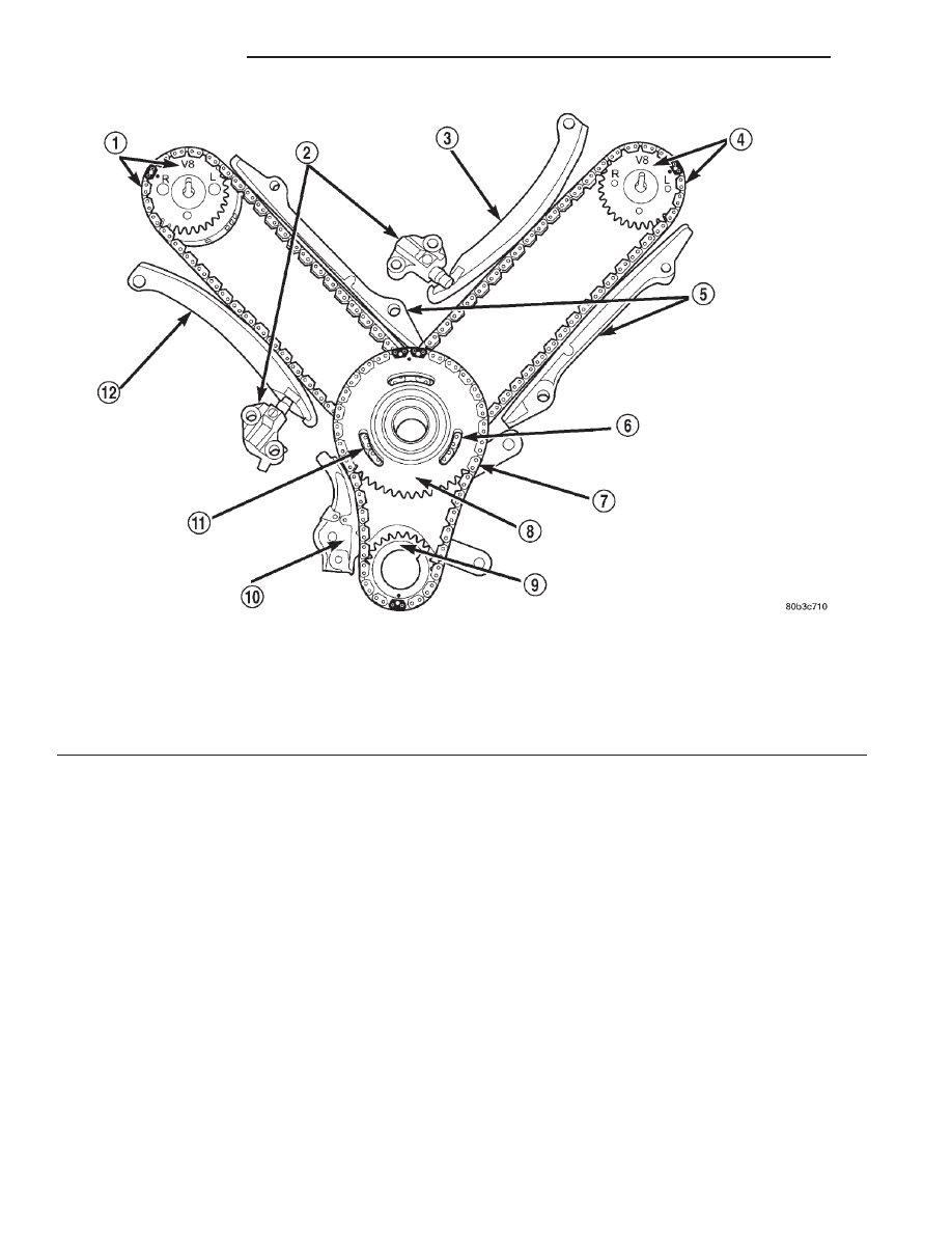
Fig. 140 Timing Chain System

1 - RIGHT CAMSHAFT SPROCKET AND SECONDARY CHAIN
2 - SECONDARY TIMING CHAIN TENSIONER (LEFT AND RIGHT
SIDE NOT COMMON)
3 - SECONDARY TENSIONER ARM
4 - LEFT CAMSHAFT SPROCKET AND SECONDARY CHAIN
5 - CHAIN GUIDE
6 - TWO PLATED LINKS ON RIGHT CAMSHAFT CHAIN

7 - PRIMARY CHAIN
8 - IDLER SPROCKET
9 - CRANKSHAFT SPROCKET
10 - PRIMARY CHAIN TENSIONER
11 - TWO PLATED LINKS ON LEFT CAMSHAFT CHAIN
12 - SECONDARY TENSIONER ARM

9 - 208

ENGINE 4.7L

AN

TIMING BELT/CHAIN AND SPROCKETS (Continued)

(9) Lubricate idler shaft and bushings with clean

engine oil.

(10) Install all chains, crankshaft sprocket, and

idler sprocket as an assembly (Fig. 143). After guid-
ing both secondary chains through the block and cyl-
inder head openings, affix chains with a elastic strap
or the equivalent, This will maintain tension on
chains to aid in installation.

NOTE: It will be necessary to slightly rotate cam-
shafts for sprocket installation.

(11) Align left camshaft sprocket “L” dot to plated

link on chain.

(12) Align right camshaft sprocket “R” dot to

plated link on chain.

CAUTION: Remove excess oil from the camshaft
sprocket bolt. Failure to do so can result in over-
torque of bolt resulting in bolt failure.

(13) Remove Special Tool 8515, then attach both

sprockets to camshafts. Remove excess oil from bolts,
then Install sprocket bolts, but do not tighten at this
time.

(14) Verify that all plated links are aligned with

the marks on all sprockets and the “V8” marks on
camshaft sprockets are at the 12 o’clock position (Fig.
140).

Fig. 141 Resetting Secondary Chain Tensioners

1 - VISE
2 - INSERT LOCK PIN
3 - RATCHET PAWL
4 - RATCHET
5 - PISTON

Fig. 142 Installing Secondary Timing Chains on

Idler Sprocket

1 - LOCK ARM
2 - RIGHT CAMSHAFT CHAIN
3 - SECONDARY CHAINS RETAINING PINS (4)
4 - IDLER SPROCKET
5 - LEFT CAMSHAFT CHAIN
6 - SPECIAL TOOL 8515

Fig. 143 Installing Idler Gear, Primary and

Secondary Timing Chains

1 - SPECIAL TOOL 8515
2 - PRIMARY CHAIN IDLER SPROCKET
3 - CRANKSHAFT SPROCKET

AN

ENGINE 4.7L

9 - 209

TIMING BELT/CHAIN AND SPROCKETS (Continued)

CAUTION: Ensure the plate between the left sec-
ondary chain tensioner and block is correctly
installed.

(15) Install

both

secondary

chain

tensioners.

Tighten bolts to 28 N·m (250 in. lbs.).

NOTE: Left and right secondary chain tensioners
are not common.

(16) Before installing idler sprocket bolt, lubricate

washer with oil, and tighten idler sprocket assembly
retaining bolt to 34 N·m (25 ft. lbs.).

(17) Remove all locking pins (3) from tensioners.

CAUTION: After pulling locking pins out of each
tensioner, DO NOT manually extend the tensioner(s)
ratchet. Doing so will over tension the chains,
resulting in noise and/or high timing chain loads.

(18) Using Special Tool 6958, Spanner with Adaptor

Pins 8346, tighten left (Fig. 144) and right (Fig. 145)
camshaft sprocket bolts to 122 N·m (90 ft. lbs.).

(19) Rotate engine two full revolutions. Verify tim-

ing marks are at the follow locations:

• primary chain idler sprocket dot is at 12 o’clock

(Fig. 140)

• primary chain crankshaft sprocket dot is at 6

o’clock (Fig. 140)

• secondary chain camshaft sprockets “V8” marks

are at 12 o’clock (Fig. 140)

(20) Lubricate all three chains with engine oil.

Fig. 144 Tightening Left Side Camshaft Sprocket

Bolt

1 - TORQUE WRENCH
2 - CAMSHAFT SPROCKET
3 - LEFT CYLINDER HEAD
4 - SPECIAL TOOL 6958 SPANNER WITH ADAPTER PINS 8346

Fig. 145 Tightening Right Side Camshaft Sprocket

Bolt

1 - TORQUE WRENCH
2 - SPECIAL TOOL 6958 WITH ADAPTER PINS 8346
3 - LEFT CAMSHAFT SPROCKET
4 - RIGHT CAMSHAFT SPROCKET

9 - 210

ENGINE 4.7L

AN

TIMING BELT/CHAIN AND SPROCKETS (Continued)

(21) After installing all chains, it is recommended

that the idler gear end play be checked (Fig. 146).
The end play must be within 0.10–0.25 mm (0.004–
0.010 in.). If not within specification, the idler gear
must be replaced.

(22) Install timing chain cover (Refer to 9 -

ENGINE/VALVE TIMING/TIMING BELT / CHAIN
COVER(S)

-

INSTALLATION)

and

crankshaft

damper (Refer to 9 - ENGINE/ENGINE BLOCK/VI-
BRATION DAMPER - INSTALLATION).

(23) Install cylinder head covers (Refer to 9 -

ENGINE/CYLINDER

HEAD/CYLINDER

HEAD

COVER(S) - INSTALLATION).

NOTE: Before installing threaded plug in right cylin-
der head, the plug must be coated with sealant to
prevent leaks.

(24) Coat the large threaded access plug with

Mopar

Thread Sealant with Teflon, then install

into the right cylinder head and tighten to 81 N·m
(60 ft. lbs.) (Fig. 135).

(25) Install the oil fill housing.
(26) Install access plug in left cylinder head (Fig.

135).

(27) Install power steering pump (Refer to 19 -

STEERING/PUMP - INSTALLATION).

(28) Install radiator fan shroud.
(29) Fill cooling system (Refer to 7 - COOLING -

STANDARD PROCEDURE).

(30) Connect negative cable to battery.

Fig. 146 Measuring Idler Gear End Play

1 - IDLER SPROCKET ASSEMBLY
2 - DIAL INDICATOR

AN

ENGINE 4.7L

9 - 211

TIMING BELT/CHAIN AND SPROCKETS (Continued)


Content   ..  503  504  505  506   ..