Dodge Dakota (R1). Manual - part 461


  Index      Dodge     Dodge Dakota (R1) - service repair manual 2000 year


Search            


Content   ..  459  460  461  462   ..


Dodge Dakota (R1). Manual - part 461


(20) Install the radiator or radiator and condenser,

if equipped with A/C.

(21) Fill the cooling system (Refer to 7 - COOLING

- STANDARD PROCEDURE).

(22) Connect negative cable to battery.

CONNECTING ROD BEARINGS

STANDARD PROCEDURE CONNECTING ROD
BEARING - FITTING

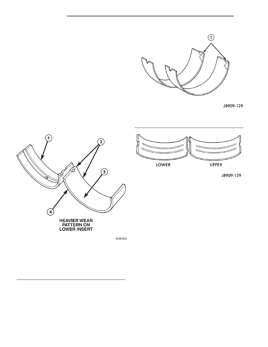
Inspect the connecting rod bearings for scoring and

bent alignment tabs (Fig. 30) (Fig. 31). Check the
bearings for normal wear patterns, scoring, grooving,
fatigue and pitting (Fig. 32) . Replace any bearing
that shows abnormal wear.

Inspect the connecting rod journals for signs of

scoring, nicks and burrs.

Misaligned or bent connecting rods can cause

abnormal wear on pistons, piston rings, cylinder
walls, connecting rod bearings and crankshaft con-
necting rod journals. If wear patterns or damage to
any of these components indicate the probability of a
misaligned connecting rod, inspect it for correct rod
alignment. Replace misaligned, bent or twisted con-
necting rods.

(1) Wipe the oil from the connecting rod journal.
(2) Use short rubber hose sections over rod bolts

during installation.

(3) Lubricate the upper bearing insert and install

in connecting rod.

(4) Use piston ring compressor to install the rod

and piston assemblies. The oil squirt holes in the
rods must face the camshaft. The arrow on the piston
crown should point to the front of the engine (Fig.
33). Verify that the oil squirt holes in the rods face
the camshaft and that the arrows on the pistons face
the front of the engine.

(5) Install the lower bearing insert in the bearing

cap. The lower insert must be dry. Place strip of Plas-
tigage across full width of the lower insert at the cen-
ter of bearing cap. Plastigage must not crumble in
use. If brittle, obtain fresh stock.

(6) Install bearing cap and connecting rod on the

journal and tighten nuts to 45 N·m (33 ft. lbs.)
torque. DO NOT rotate crankshaft. Plastigage will
smear, resulting in inaccurate indication.

(7) Remove the bearing cap and determine amount

of bearing-to-journal clearance by measuring the
width of compressed Plastigage (Fig. 34). (Refer to 9 -
ENGINE - SPECIFICATIONS) for the proper clear-
ance. Plastigage should indicate the same clear-

Fig. 30 Connecting Rod Bearing Inspection

1 - UPPER BEARING HALF
2 - MATING EDGES
3 - GROOVES CAUSED BY ROD BOLTS SCRATCHING
JOURNAL DURING INSTALLATION
4 - WEAR PATTERN — ALWAYS GREATER ON UPPER
BEARING
5 - LOWER BEARING HALF

Fig. 31 Locking Tab Inspection

1 - ABNORMAL CONTACT AREA CAUSED BY LOCKING TABS
NOT FULLY SEATED OR BEING BENT

Fig. 32 Scoring Caused by Insufficient Lubrication

9 - 32

ENGINE 2.5L

AN

CAMSHAFT & BEARINGS (IN BLOCK) (Continued)

ance across the entire width of the insert. If the
clearance varies, it may be caused by either a
tapered journal, bent connecting rod or foreign
material trapped between the insert and cap or
rod.

(8) If the correct clearance is indicated, replace-

ment of the bearing inserts is not necessary. Remove
the Plastigage from crankshaft journal and bearing
insert. Proceed with installation.

(9) If

bearing-to-journal

clearance

exceeds

the

specification, install a pair of 0.0254 mm (0.001 inch)
undersize bearing inserts. All the odd size inserts
must be on the bottom. The sizes of the service
replacement bearing inserts are stamped on the

backs of the inserts. Measure the clearance as
described in the previous steps.

(10) The clearance is measured with a pair of

0.0254 mm (0.001 inch) undersize bearing inserts
installed. This will determine if two 0.0254 mm
(0.001 inch) undersize inserts or another combination
is needed to provide the correct clearance Refer to
CONNECTING ROD BEARING FITTING CHART .

CONNECTING ROD BEARING FITTING CHART

CRANKSHAFT JOURNAL

CORRESPONDING CONNECTING ROD BEARING INSERT

Color Code

Diameter

Upper Insert Size

Lower Insert Size

Yellow

53.2257-53.2079 mm

Yellow - Standard

Yellow - Standard

(2.0955-2.0948 in.)

Orange

53.2079 - 53.1901 mm

Yellow - Standard

Blue - Undersize

(2.0948 - 2.0941 in.)

0.025 mm (0.001 in.)

0.0178 mm (0.0007 in.)

Undersize

Blue

53.1901 - 53.1724 mm

Blue - Undersize

Blue - Undersize

(2.0941 - 2.0934 in.)

0.025 mm (0.001 in.)

0.025 mm (0.001 in.)

0.0356 mm (0.0014 in.)

Undersize

Red

52.9717 - 52.9539 mm

Red - Undersize

Red - Undersize

(2.0855 - 2.0848 in.)

0.254 mm (0.010 in.)

0.254 mm (0.010 in.)

0.254 mm (0.010 in.)

Undersize

Fig. 33 Rod and Piston Assembly Installation

Fig. 34 Measuring Bearing Clearance

1 - PLASTIGAGE SCALE
2 - COMPRESSED PLASTIGAGE

AN

ENGINE 2.5L

9 - 33

CONNECTING ROD BEARINGS (Continued)

(11) FOR EXAMPLE: If the initial clearance was

0.0762 mm (0.003 inch), 0.025 mm (0.001 inch)
undersize inserts would reduce the clearance by
0.025 mm (0.001 inch). The clearance would be 0.002
inch and within specification. A 0.051 mm (0.002
inch) undersize insert would reduce the initial clear-
ance an additional 0.013 mm (0.0005 inch). The
clearance would then be 0.038 mm (0.0015 inch).

(12) Repeat the Plastigage measurement to verify

your bearing selection prior to final assembly.

(13) Once you have selected the proper insert,

install the insert and cap. Tighten the connecting rod
bolts to 45 N·m (33 ft. lbs.) torque. Slide snug-fitting
feeler gauge between the connecting rod and crank-
shaft journal flange (Fig. 35). (Refer to 9 - ENGINE -
SPECIFICATIONS) for the proper clearance. Replace
the connecting rod if the side clearance is not within
specification.

CRANKSHAFT

DESCRIPTION

The crankshaft (Fig. 36) is of a forged steel design,

with five main bearing journals and eight counter
balance weights.The crankshaft is located at the bot-
tom of the engine block and is held in place with five
main bearing caps.

OPERATION

The crankshaft transfers force generated by com-

bustion within the cylinder bores to the flywheel or
flexplate.

REMOVAL

(1) Remove the oil pan (Refer to 9 - ENGINE/LU-

BRICATION/OIL PAN - REMOVAL).

(2) Remove the oil pump from the rear main bear-

ing cap.

(3) Remove the vibration damper (Refer to 9 -

ENGINE/ENGINE BLOCK/VIBRATION DAMPER -
REMOVAL).

(4) Remove the timing chain cover (Refer to 9 -

ENGINE/VALVE TIMING/TIMING BELT / CHAIN
COVER(S) - REMOVAL).

(5) Identify bearing caps before removal. Remove

bearing caps and bearings one at a time.

(6) Lift the crankshaft out of the block.
(7) Remove and discard the crankshaft rear oil

seals.

(8) Remove and discard the front crankshaft oil

seal.

INSTALLATION

(1) Lightly oil the new upper seal lips with engine

oil.

(2) Install the new upper rear bearing oil seal with

the white paint facing towards the rear of the engine.

(3) Position the crankshaft into the cylinder block.
(4) Lightly oil the new lower seal lips with engine

oil.

(5) Install the new lower rear bearing oil seal into

the bearing cap with the white paint facing towards
the rear of the engine.

(6) Apply 5 mm (0.20 in) drop of Mopar

t Gasket

Eliminator, or equivalent, on each side of the rear
main bearing cap (Fig. 37). DO NOT over apply seal-
ant or allow the sealant to contact the rubber seal.
Assemble bearing cap to cylinder block immediately
after sealant application.

Fig. 35 Checking Connecting Rod Side Clearance -

Typical

Fig. 36 Crankshaft 3.9L Engine

1 - MAIN BEARING JOURNALS
2 - COUNTER BALANCE WEIGHTS

9 - 34

ENGINE 2.5L

AN

CONNECTING ROD BEARINGS (Continued)

(7) To align the bearing cap, use cap slot, align-

ment dowel and cap bolts. DO NOT remove excess
material after assembly. DO NOT strike rear cap
more than 2 times for proper engagement.

(8) Clean and oil all cap bolts. Install all main

bearing caps. Install all cap bolts and alternately
tighten to 115 N·m (85 ft. lbs.) torque.

(9) Install oil pump (Refer to 9 - ENGINE/LUBRI-

CATION/OIL PUMP - INSTALLATION).

(10) Install the timing chain cover (Refer to 9 -

ENGINE/VALVE TIMING/TIMING BELT / CHAIN
COVER(S) - INSTALLATION).

(11) Install the vibration damper (Refer to 9 -

ENGINE/ENGINE BLOCK/VIBRATION DAMPER -
INSTALLATION).

(12) Apply Mopar

t Silicone Rubber Adhesive Seal-

ant, or equivalent, at bearing cap to block joint to
provide cap to block and oil pan sealing (Fig. 38).
Apply enough sealant until a small amount is
squeezed out. Withdraw nozzle and wipe excess seal-
ant off the oil pan seal groove.

(13) Install new front crankshaft oil seal (Refer to

9 - ENGINE/ENGINE BLOCK/CRANKSHAFT OIL
SEAL - FRONT - INSTALLATION).

(14) Immediately install the oil pan (Refer to 9 -

ENGINE/LUBRICATION/OIL

PAN

-

INSTALLA-

TION).

CRANKSHAFT MAIN
BEARINGS

DESCRIPTION

Main bearings (Fig. 39) are located in the cylinder

block. One half of the main bearing is located in the
crankshaft main bore the other half of the matching
bearing is located in the main bearing cap. there are
five main bearings. Number two main bearing is
flanged, this flange controls crankshaft thrust.

OPERATION

The main bearings encircle the crankshaft main

bearing journals, this aligns the crankshaft to the
centerline of the engine and allows the crankshaft to
turn without wobbling or shaking therefore eliminat-
ing vibration. The main bearings are available in
standard and undersizes.

Fig. 37 Sealant Application to Bearing Cap

1 - MOPAR SILICONE RUBBER ADHESIVE SEALANT SLOTS
2 - MOPAR

T

GASKET MAKER (OR EQUIVALENT)

3 - CAP ALIGNMENT SLOT
4 - REAR MAIN BEARING CAP

Fig. 38 Apply Sealant to Bearing Cap to Block

1 - MOPAR

T

GEN II SILICONE RUBBER ADHESIVE SEALANT

NOZZLE TIP
2 - SEALANT APPLIED
3 - CYLINDER BLOCK
4 - REAR MAIN BEARING CAP

Fig. 39 Main Bearing Orientation

AN

ENGINE 2.5L

9 - 35

CRANKSHAFT (Continued)


Content   ..  459  460  461  462   ..